Optical System for a Video Endoscope and Video Endoscope

a technology of optical system and video endoscope, which is applied in the field of optical system of video endoscope and optical system therefor, can solve the problems of unreliable fluorescence imaging, unreliable fluorescence observation and imaging, and false interpretation of fluorescence signal

Pending Publication Date: 2022-04-07
KARL STORZ GMBH & CO KG
View PDF0 Cites 0 Cited by
  • Summary
  • Abstract
  • Description
  • Claims
  • Application Information

AI Technical Summary

Benefits of technology

[0013]The shortcomings of the prior art are solved by the presented, inventive optical system for a video endoscope that comprises at least one electronic image sensor, wherein the image sensor is an active pixel sensor with a progressive offset of a micro-lens array, and a lens system with at least one lens, a second lens, a third lens and / or further lenses in order from an object side to receive an image light from an object field and to direct the image light to the at least one image sensor arranged in an image plane of the optical system, where at least one filter coating is located at and / or on a support element for forming an interference filter at a position in the optical system, such that the angle of incidence of the image light on the filter coating is minimized and fluorescence imaging is thereby possible.

Problems solved by technology

However, the combination of a short optical system and a commonly mass-produced CMOS-sensor in endoscopes causes specific problems concerning the progression of rays within the optical system that is particularly troubling to reliable fluorescence imaging.
However, in endoscopes with a short optical system that meets the steep chief ray angle requirement of a CMOS sensor's micro lens array, such positioning of an interference filter is not possible.
This creates a problem, as interference filters generally change their band of transmission as the angle of incidence diverges from a perpendicular to the surface of the interference filter.
Due to this shift towards shorter wavelengths, the commonly shorter excitation wavelength in fluorescence imaging can pass the interference filter and thus overlays and interferes with the emission wavelength from the fluorophore, resulting in unreliable fluorescence observation and imaging as well as false interpretation of the fluorescence signal.
This can have major consequences, such as the inability to reliably recognize the boundaries of a tumor in a medical application or the proper detection of bacteria, for example, in industrial applications.
In short optical systems, due to the adaption of the objective to the high chief ray angle progression of the electronic image sensor and therefore the high angle of incidence within the optical system for a major part of the field of view, commonly known interference filters cannot be used, at least as conventionally positioned.
In general, commonly known interference filters can only be optimized for a specific angle of incidence and a specific wavelength.
This CRA requirement can be interpreted as a “field-dependent offset” of the AOI, making the problems associated with a large AOI much more challenging.
As the optical apparatus of US 2014 / 0211073 A1 uses lenses in a telecentric configuration, an adaptation of the ray progression within the optical assembly to steep chief ray angles of a CMOS-sensor is not possible.

Method used


Image

  • Optical System for a Video Endoscope and Video Endoscope
  • Optical System for a Video Endoscope and Video Endoscope
  • Optical System for a Video Endoscope and Video Endoscope

Examples


Embodiment Construction

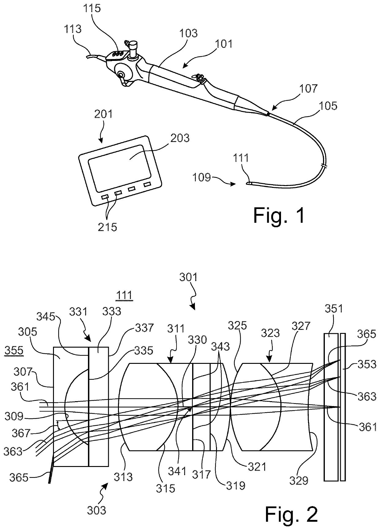
[0074]A video endoscope 101 shown in FIG. 1 comprises a handle 103 and an elongate shaft 105 connectable to each other at a proximal end 107 of the shaft 105. The handle 103 comprises operator controls 115 and is connected via a cable 113 at its proximal end to an external, non-shown control and processing unit and to a display system 201 shown in FIG. 1. The display system 201 includes a monitor 203 for displaying endoscopic images and operator controls 215.

[0075]The video endoscope 101 is designed to provide video and image data from an object field within a cavity of a non-shown body. For this, the elongate shaft 105 comprises, at its distal end 109, a distal end section 111.

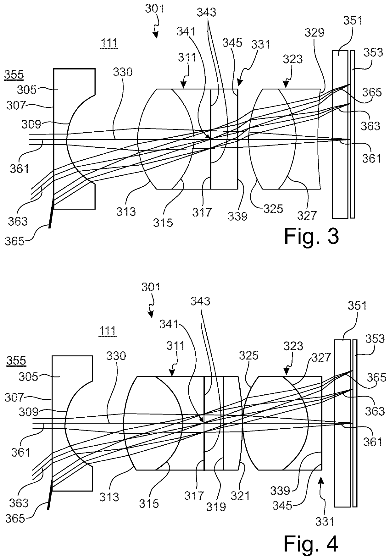
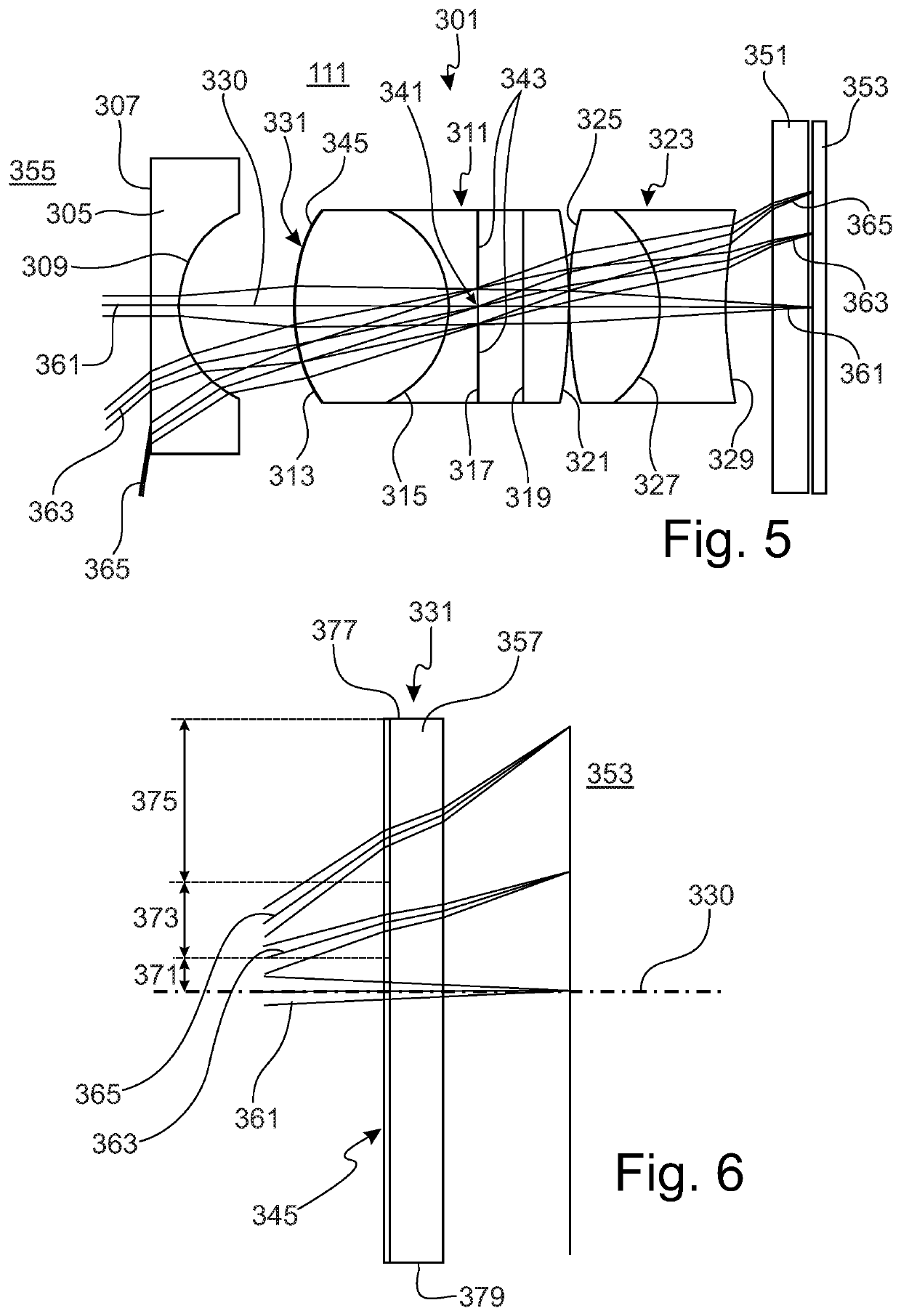
[0076]The distal end section 111 of the elongate shaft 105 comprises an optical system 301, as shown in FIGS. 2-5, and an image sensor 353 with a glass plate 351. The optical system 301 comprises an objective lens system 303 with a first lens 305, second combined lenses 311 and third combined lenses 323 in di...


PUM

PropertyMeasurementUnit
angle of incidenceaaaaaaaaaa

Abstract

The invention concerns an optical system, and a video endoscope therefor, with at least one electronic active pixel image sensor with a progressive offset micro-lens array, and a lens system with a plurality of lenses in order to receive image light from an object field and direct it to the image sensor. The optical system has at least one interference filter coating located within the optical system, such that the angle of incidence of the image light on the filter coating is minimized, minimizing thereby the filtration characteristics of the coating that are angularly dependent. This minimization improves the reliability of fluorescence imaging with short optical systems. The location for the filter coating may be on a curved surface, such as a lens, or on a properly positioned flat element within the optical system.

Description

CROSS REFERENCE TO RELATED APPLICATIONS[0001]This application claims priority to German Patent Application No. 102021106839.8, filed Mar. 19, 2021, and German Patent Application No. 102020125854.2, filed Oct. 2, 2020, both of which are incorporated by reference.FIELD OF THE INVENTION[0002]The invention concerns video endoscopes and optical systems therefor, and more particularly to video endoscopes used for visible and fluorescent imaging (FI). This invention is particularly relevant to distal tip video endoscopes with short optical systems and those wherein the image sensor is an active pixel sensor with a progressive offset of a micro-lens array.BACKGROUND OF THE INVENTION[0003]For medical or non-medical applications, endoscopes comprise an elongate shaft configured to be introduced into an internal cavity of a human or animal body or another object for examination, such as a piping. Non-medical endoscopes are often referred to as borescopes. For generating an image of an object f...

Claims


Application Information

Patent Timeline
Patent Type & Authority Applications(United States)
IPC IPC(8): G02B23/24G02B13/00G02B3/00G02B1/12G02B5/28
CPCG02B23/243G02B13/0035G02B5/28G02B3/0043G02B1/12G02B23/2484A61B1/043A61B1/05A61B1/00096A61B1/00186G02B23/2423G02B23/2446G02B2207/113G02B5/283
Inventor BAUMANN, HARALDHÄSLER, BENJAMINHOFSTETTER, MARCEL
Owner KARL STORZ GMBH & CO KG
Why Eureka
Try Eureka