
Switching power supply apparatus

a power supply and power supply technology, applied in the direction of electric variable regulation, process and machine control, instruments, etc., can solve the problems of inaccurate detection of current, inability to use circuit elements in power conversion circuits, and inapplicability of circuits, etc., to achieve high current detection accuracy, simple circuit configuration, and high efficiency of power conversion

Pending Publication Date: 2022-04-28
MURATA MFG CO LTD
View PDF0 Cites 0 Cited by
  • Summary
  • Abstract
  • Description
  • Claims
  • Application Information

AI Technical Summary

Benefits of technology

The patent text describes a new technology for a compact switching power supply that can detect the current accurately and efficiently convert power. The technology solves the problem of decreased accuracy caused by changes in input voltage or load, or by heat generation or temperature variation. The technology is simple and requires a small number of components, making it highly practical for various power conversion needs.

Problems solved by technology

For example, although such a circuit may be a solution for accurate current detection in the case of low current of 10 A or low, the circuit is not practical in the case of high current in consideration of the circuit size and the power loss.
However, the circuit configuration using the circuit element in the power conversion circuit has several problems.
Accordingly, the current is not accurately detected by only detecting the voltage between both ends of the on resistance of a low-side MOSFET.
The technology that uses the direct-current resistance (DCR) of the inductor for the current detection has a problem in that the accuracy of the current detection is greatly decreased when the input voltage or a load in the power conversion circuit is varied.
Although a current detection signal can be corrected in accordance with the variation in input voltage or a load, the circuit is increased in size and is made complicated and the power efficiency is reduced due to an occurrence of power consumption in a peripheral circuit to greatly reduce the usefulness.
In addition, when the power conversion circuit operates to cause heat generation in the inductor or variation in ambient temperature of the inductor, there is a problem in that the accuracy of the current detection is greatly decreased.
Although the current detection signal can be corrected in accordance with the temperature of the inductor or the variation of the ambient temperature of the inductor in order to resolve this problem, the circuit is increased in size and is made complicated and the power efficiency is reduced due to an occurrence of power consumption in the peripheral circuit to greatly reduce the usefulness.

Method used


Image

  • Switching power supply apparatus
  • Switching power supply apparatus
  • Switching power supply apparatus

Examples


first embodiment

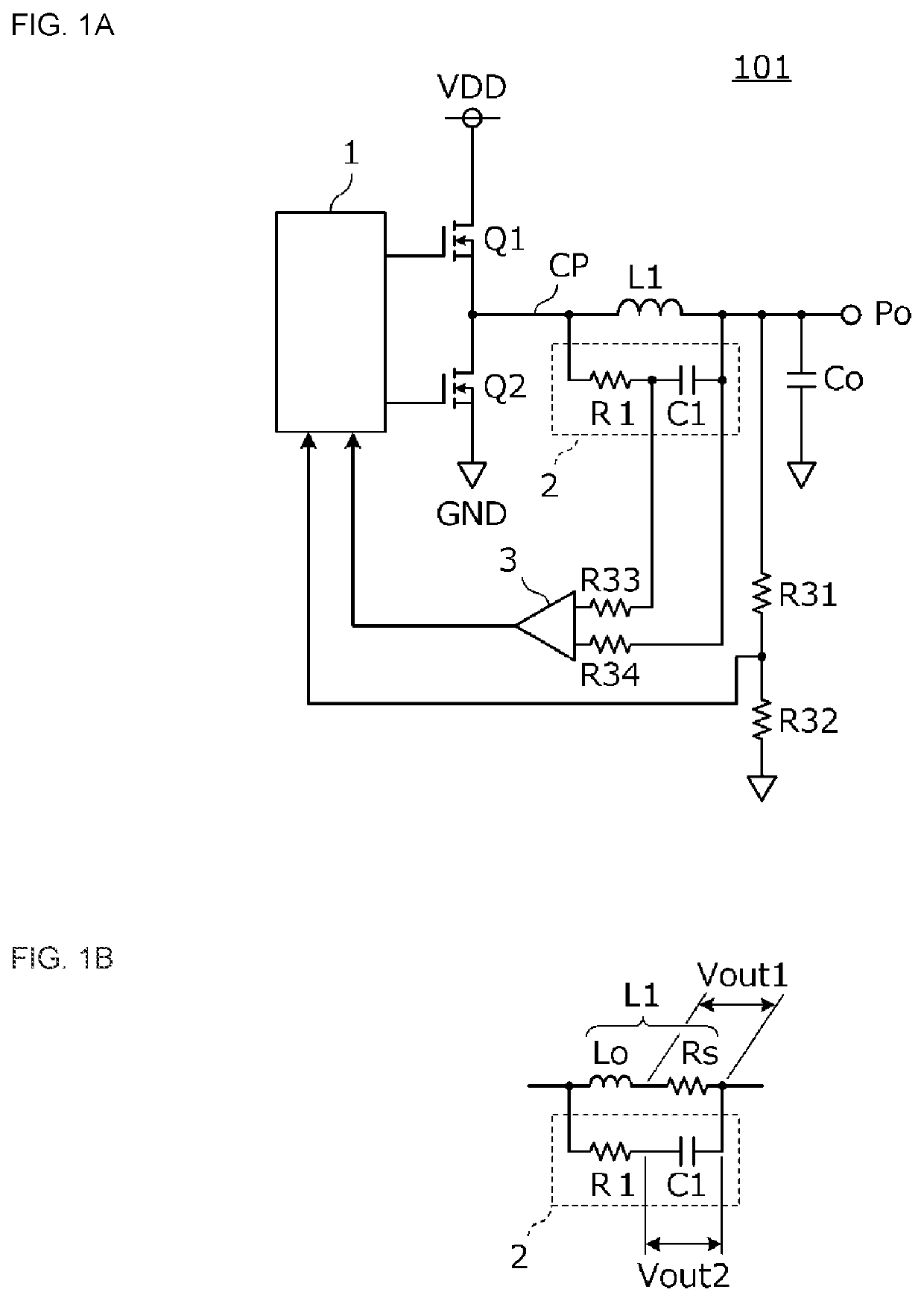
[0032]FIG. 1A and FIG. 1B are circuit diagrams of a switching power supply apparatus according to a first embodiment. A switching power supply apparatus 101 includes an inductor L1, a capacitor Co, switching elements Q1 and Q2, a switching control circuit 1, an inductor current detection circuit 2, a differential amplifier circuit 3, and resistive elements R31, R32, R33, and R34. VDD denotes a power supply voltage terminal and GND denotes a ground terminal.

[0033]The inductor L1 is connected in series to a current path CP through which current is supplied to an output portion Po. The capacitor Co is connected in parallel to the output portion Po (connected between a voltage output end of the output portion Po and ground). The switching elements Q1 and Q2 generate switching current flowing through the inductor L1. The switching control circuit 1 performs switching control of the switching elements Q1 and Q2. The inductor current detection circuit 2 detects current flowing through the ...

second embodiment

[0070]In a second embodiment, an example of a power system is described, which is configured so that the inductor current of each cell converter is detected to attain current balancing in a switching power supply apparatus having a multicell converter configuration.

[0071]FIG. 8 is a circuit diagram of the power system according to the second embodiment. This power system includes two cell converters 11 and 12 and a microprocessor 5 controlling the cell converters 11 and 12. The cell converters 11 and 12 each include the inductor L1, a capacitor Ci, the capacitor Co, the switching elements Q1 and Q2, the switching control circuit 1, the inductor current detection circuit 2, and a load balancing controller 4.

[0072]The load balancing controller 4 detects voltage at the output portion Po and supplies a feedback signal to the switching control circuit 1 so that the output voltage has a certain value. The two load balancing controllers 4 are connected to each other with a current sharing ...

third embodiment

[0076]In a third embodiment, an example of a power system is described, which is configured so that the inductor current of each cell converter is detected to attain current balancing in a switching power supply apparatus having a multiphase converter configuration.

[0077]FIG. 10 is a circuit diagram of the power system according to the third embodiment. This power system includes six cell converters and the microprocessor 5 controlling the six cell converters. Each cell converter includes a switching circuit DD, the load balancing controller 4, the resistive elements R31 and R32, the inductor L1, and an inductor current detection circuit composed of the detection resistor R1 and the detection capacitor C1. The switching circuit DD is composed of a switching element and a switching control circuit. The switching circuit DD performs a switching operation when an enable signal input into an enable signal terminal EN is valid and stops the switching operation when the enable signal is i...


PUM


Abstract

A switching power supply apparatus includes switching elements that generate switching current flowing through an inductor, a switching control circuit, and an inductor current detection circuit that detects current flowing through the inductor. The inductor current detection circuit is composed of a time constant circuit including a detection capacitor and a detection resistor that are connected in series to each other and is connected in parallel to the inductor. A time constant of the inductor current detection circuit has characteristics varied with frequency or temperature. This compensates variation of equivalent series resistance of the inductor with respect to the frequency or variation thereof with respect to the temperature.

Description

CROSS-REFERENCE TO RELATED APPLICATIONS[0001]This application claims benefit of priority to International Patent Application No. PCT / JP2020 / 005034, filed Feb. 10, 2020, and to Japanese Patent Application No. 2019-127565, filed Jul. 9, 2019, the entire contents of each are incorporated herein by reference.BACKGROUNDTechnical Field[0002]The present disclosure relates to a switching power supply apparatus including an inductor and an inductor current detection circuit that detects switching current flowing through the inductor.Background Art[0003]In switching power supply apparatuses, detection of current flowing through inductors with high accuracy is increased in importance. For example, a power supply apparatus that supplies power supply voltage for a processor is required to have lower voltage and higher current with the decreasing operation voltage of the processor. In such a power supply apparatus outputting high current, high current flows through the inductor in the power suppl...

Claims


Application Information

Patent Timeline
Patent Type & Authority Applications(United States)
IPC IPC(8): H02M3/158H02M1/00
CPCH02M3/158H02M1/0009H02M3/1586H02M1/0048Y02B70/10
Inventor HOSOTANI, TATSUYA
Owner MURATA MFG CO LTD
Learn More