Balun

a technology of balanced signal and waveguide, applied in the field of balanced signal, can solve the problems of large substrate area, unbalanced signal, unsuitable for miniaturization of the entire device, etc., and achieve the effect of widening the band width and improving the balance characteristics

Pending Publication Date: 2022-06-02
MURATA MFG CO LTD
View PDF0 Cites 1 Cited by
  • Summary
  • Abstract
  • Description
  • Claims
  • Application Information

AI Technical Summary

Benefits of technology

[0008]Preferred embodiments of the present invention each improve balance characteristics while achieving miniaturization and a wider band width in a balun to be used in a communication device.
[0013]According to each of preferred embodiments of the present invention, a configuration is provided in which at least one of two balanced lines (e.g., a second line and a third line) coupled to the first line connected to the unbalanced terminal is further coupled with a signal of the other balanced line. With such a configuration, it is possible to improve balance characteristics while achieving miniaturization and a wider band width.

Problems solved by technology

On the other hand, an unbalanced signal is a signal to be used in a transmission system for transmitting a change in potential with respect to a ground potential, and an input / output signal of a microstrip line or an antenna corresponds to the unbalanced signal.
In these baluns, it is necessary to form lines to be coupled with each other in the same substrate, so that the substrate area becomes large, which is not suitable for miniaturization of the entire device.
In addition, a matched filter balun formed by coupling an inductor included in a low pass filter connected to an unbalanced line and an inductor included in a high pass filter connected to each of two balanced lines is suitable for miniaturization, but has a problem that a usable frequency band width is relatively narrow.

Method used


Image

  • Balun
  • Balun
  • Balun

Examples


embodiment 1

Preferred Embodiment 1

Overview of Communication Device

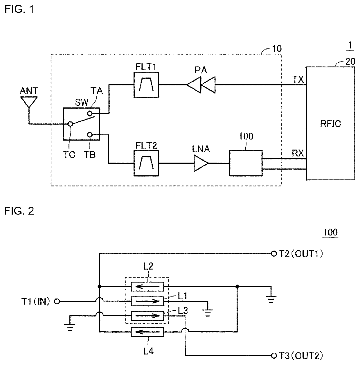
[0034]FIG. 1 is a block diagram of a communication device 1 including a front-end circuit 10 in which a balun 100 according to Preferred Embodiment 1 is provided. With reference to FIG. 1, the communication device 1 includes an antenna ANT and an RFIC 20 defining and functioning as a signal processing circuit in addition to the front-end circuit 10.

[0035]The RFIC 20 outputs a radio frequency signal to a transmission-side line TX, and radiates a radio wave from the antenna ANT via the front-end circuit 10. Further, the RFIC 20 receives a radio wave received by the antenna ANT from a reception-side line RX, processes the received signal, and transmits the processed signal to a circuit at a subsequent stage.

[0036]The front-end circuit 10 includes a switch SW, filters FLT1 and FLT2, a power amplifier PA, and a low-noise amplifier LNA in addition to the balun 100. The switch SW is used to switch between transmission and reception of r...

embodiment 2

Preferred Embodiment 2

[0079]In Preferred Embodiment 1 and the modification thereof, the case where the impedance of the device connected to the balanced terminal is equal to or higher than the impedance of the device connected to the unbalanced terminal has been described.

[0080]On the other hand, the impedance of the device connected to the balanced terminal may be set lower than the impedance of the device connected to the unbalanced terminal. In this case, in general, a desired impedance ratio is achieved by decreasing the number of turns of the coil of the balanced line in the balun, increasing the number of turns of the coil of the unbalanced line, or increasing the capacitance of the capacitor C1 to adjust a wavelength. However, when the impedance of the balanced line side is set to be low, it is necessary to further increase the degree of capacitive coupling between the unbalanced line and the balanced line in order to match the resonant frequency of the balanced line with the...

embodiment 3

Preferred Embodiment 3

[0099]In the examples of the baluns described in Preferred Embodiment 1 and Preferred Embodiment 2, as illustrated in FIG. 6 and FIG. 13, a configuration in which each line includes the coil extending across two layers has been described. When the balun is used in a low-frequency region, it may be necessary to further increase the line length of the coil. In this case, depending on the frequency to be used, a desired line length cannot be achieved with two layers, and it may be necessary to form a coil across more layers.

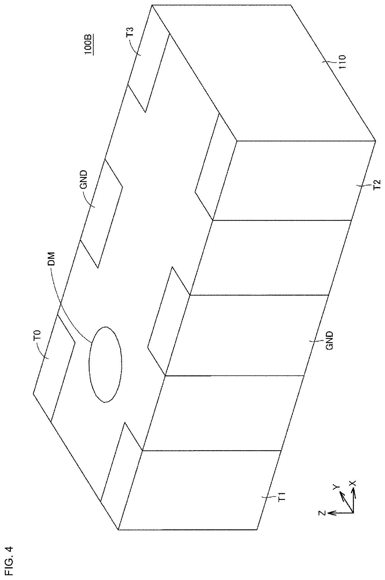
[0100]Here, when an outer electrode to be used for connection to an external device is provided at a side surface of a dielectric substrate (see FIG. 4) as in an example of a balun according to a preferred embodiment of the present invention, it is preferable that an end portion of each line connected to the outer electrode is positioned at an outer peripheral portion of each dielectric layer. However, when a spiral coil includes an odd number ...


PUM

PropertyMeasurementUnit
impedancesaaaaaaaaaa
impedance ratioaaaaaaaaaa

Abstract

A balun includes an unbalanced terminal, balanced terminals, and lines, and converts a signal between an unbalanced line and an balanced line. A first line is connected between the unbalanced terminal and a reference potential. A second line is connected between the balanced terminal and the reference potential, and is coupled to the first line. A third line is connected between the balanced terminal and the reference potential, and is coupled to the first line. A fourth line is connected in parallel to the second line, and is coupled to the third line. The fourth line is configured such that a signal with an opposite phase to that of a signal passing through the third line passes through the fourth line.

Description

CROSS REFERENCE TO RELATED APPLICATIONS[0001]This application claims the benefit of priority to Japanese Patent Application No. 2019-168313 filed on Sep. 17, 2019 and Japanese Patent Application No. 2020-033545 filed on Feb. 28, 2020, and is a Continuation Application of PCT Application No. PCT / JP2020 / 026385 filed on Jul. 6, 2020. The entire contents of each application are hereby incorporated herein by reference.BACKGROUND OF THE INVENTION1. Field of the Invention[0002]The present disclosure relates to a balun that converts a signal between an unbalanced line and a balanced line, and more particularly relates to a structure for improving characteristics in a laminated balun.2. Description of the Related Art[0003]A balun is a converter to be used for mutual conversion between an unbalanced signal and a balanced signal. A balanced signal is a pair of signals having equal amplitudes and mutually opposite phases, and is generally used in a differential amplifier circuit or the like in ...

Claims


Application Information

Patent Timeline
Patent Type & Authority Applications(United States)
IPC IPC(8): H03H7/42H01F27/28
CPCH03H7/42H01F2027/2809H01F27/2804H01P5/10H03H2001/0085H03H7/422H01F19/04
Inventor SATO, TAKUYA
Owner MURATA MFG CO LTD
Why Eureka
Try Eureka