
Thermal barrier material for a rechargeable electrical energy storage system

a technology of electrical energy storage and thermal barrier material, which is applied in the direction of inorganic insulators, batteries, cell components, etc., can solve the problems of unwanted effects, overheating and then thermal runaway, and further increase of reaction rate and in turn of generated heat, etc., and achieves the effect of convenient us

Active Publication Date: 2022-08-18
3M INNOVATIVE PROPERTIES CO
View PDF0 Cites 2 Cited by
  • Summary
  • Abstract
  • Description
  • Claims
  • Application Information

AI Technical Summary

Benefits of technology

The patent text describes a need for materials and arrangements that can prevent or delay heat transfer and propagation in rechargeable electrical energy storage systems. The current materials used for this purpose have limitations, such as being flammable or ineffective in insulating against heat. The technical effect of this patent text is to provide a solution that can protect against thermal runaway events and be easily used in designing rechargeable electrical energy storage systems.

Problems solved by technology

This internal overheating can lead to a so called “thermal runaway” when the reaction rate within the cell caused by the high temperature increases to a point where more heat is generated within the cell than can be withdrawn and the generated heat leads to a further increase of the reaction rate and in turn of the generated heat.
In particular, it is essential in such cases to interrupt or at least reduce a heat transfer from defective cells or cell packs to other parts of the storage system or around the storage system, because the heat generated in a defective battery cell or cell pack can spread out to the neighboring cells, which in turn can cause overheat and then undergo thermal runaway.
Also, it is important to limit the heat transfer to parts around the storage system, which may get destroyed or harmed when treated with the above-mentioned temperatures, causing electrical shortages which in turn could lead to unwanted effects as further cells getting into a thermal runaway.
Both can be damaged as soon as temperatures of 600° C. and above are reached.
Even steel casings may be at risk in certain situations such as for example a deformation of the casing due to an accident or a malfunctioning of an electrical insulation material.
There is a risk that heat, and gas gets out of the housing as soon as there is a thermal runaway event within the housing that reaches temperatures that are higher than 600° C.
If such bigger storage systems get defective, the following reactions might also get more intense, because of the higher energy stored in those systems.
This might lead to higher temperatures.
If operation occurs outside the bounds of the specified range, then damage or accelerated degradation of the cells within the battery occurs.
A catastrophic phenomenon called thermal runaway propagation occurs when one cell in a battery module catches on fire because it is punctured, damaged, or faulty in its operation.
These fires can be potentially massive, especially in high power devices such as electric vehicles, where it is common to see battery packs containing tens, hundreds, or even thousands, of individual cells.
Such fires are not limited to the battery and can spread to surrounding structures and endanger occupants of the vehicle or other structures in which these batteries are located.
Protecting against the dangers associated with a sudden thermal runaway event in an electric vehicle battery is a significant technical challenge.
One problem in devising a universal solution is that materials that work well in protecting against one aspect of thermal runaway fall short in other ways.
Heat shield materials made from woven non-combustible fibers (e.g., inorganic fibers) can be effective in preventing penetration of a fire but tend to be too thin to adequately insulate against the intense heat of a fire or to absorb / deflect debris that is launched when a cell explodes.
Using thicker layers of heat shield materials is generally not cost effective.
Combinations of these materials could work, but it can be difficult to bond these materials to each other, particularly when the selection of bonding materials may be constrained by flammability issues.
Another technical difficulty arises when using fibers and foams used in conventional thermal management systems.
Even fire-resistant fibers and foams are prone to melting at sufficiently high temperatures, for example, greater than 600° C.
Fibers and foams that would not melt during such thermal runaway events (e.g., oxidized polyacrylonitrile) tend to be relatively brittle and can introduce new problems associated with fiber shedding or loose material during product manufacture, intermediate handling, and use.
Current test methods insufficiently determine how a material alone or in combination with other materials may be effectively used as barriers in electric vehicle compartments to provide blast and thermal resistance protection.
Also, current test methods use the actual battery components including cells and modules, which is expensive and time consuming.

Method used

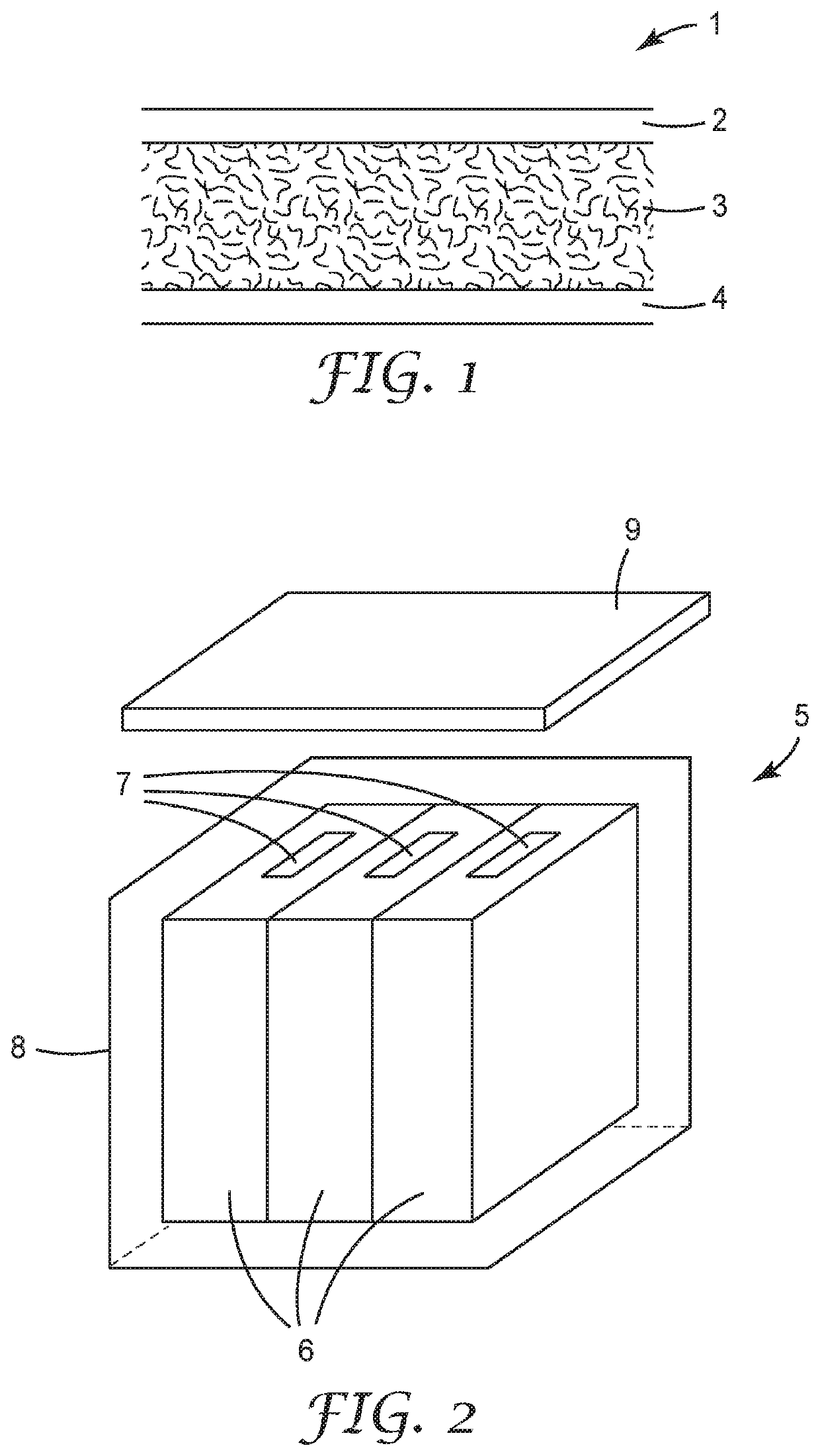

Image

  • Thermal barrier material for a rechargeable electrical energy storage system

Examples


examples 1-3 (

EX1-EX3)

[0112]The multilayer laminates of Examples 1-3 were prepared by spraying 3M Display Mount spray adhesive onto a fabric. A fiber mat was placed the fabric on top and then rolled with a 4.54 kg (10 lbs.) roller. Sample constructions are represented in Table 1 and test performance data are provided in Table 2.

examples 4-6 (

EX4-EX6)

[0113]The multilayer laminates of Examples 4-6 were prepared by using a #30 Mayer rod to draw down and apply K® sodium silicate adhesive onto a CEQUIN I inorganic insulating paper material. The inorganic fabric layer was then placed on top of the inorganic adhesive layer and then rolled with a 4.54 kg (10 lbs.) roller. The multilayer laminate was then dried at 82° C. (180° F.) for five minutes. For example, EX6, a second layer of the K® sodium silicate adhesive was applied to the other side of the CEQUIN I inorganic insulating paper using a #30 Mayer rod. A second inorganic fabric layer was then placed on top of the second inorganic adhesive layer, rolled down with a 4.54 kg (10 lbs.) roller and dried at 82° C. (180° F.) for five minutes. Sample constructions are represented in Table 1, selected physical, mechanical and electrical properties are provided in Table 2, and Thermal / flame barrier test performance data are provided in Table 3.

TABLE 1Sample Constructions for Exampl...

examples 7-13 (

EX7-EX13)

[0117]Multilayer laminates of Examples 7-13 were prepared by using a #30 Mayer rod to draw down and apply the inorganic or modified inorganic adhesive onto a 20 mil CEQUIN I inorganic insulating paper material. A layer of TG 430 glass cloth fabric was then placed on top and rolled down with a 4.54 kg (10 lbs.) roller. The multilayer laminate was dried at 180° F. (82° C.) for 5 minutes. Example 14 was prepared following the same procedure as Example EX7-EX13 except that SC2025 calcium silicate coated fiberglass fabric was bonded to 20 mil CEQUIN I inorganic insulating paper material with a KSS inorganic adhesive in place of TG430 glass cloth fabric. Sample constructions are represented in Table 4 and test performance data are provided in Table 5.

TABLE 4Sample Constructions for Examples 7-14 and Comparative ExamplesLaminate BasisLaminateWeight Thickness ExampleLamination Adhesive*(gsm)(mm)EX7100 wt. % KSS  938.5 0.88EX899.96 wt. % KSS and 0.04 wt. %   896.7 0.92SELVOL 9-325EX...


PUM

PropertyMeasurementUnit
thicknessaaaaaaaaaa
total thicknessaaaaaaaaaa
thermal conductivityaaaaaaaaaa

Abstract

A multilayer material for use as a thermal insulation barrier and / or flame barrier in a rechargeable electrical energy storage system is provided. The multilayer material comprises at least one inorganic fabric layer bonded to a nonwoven layer comprising inorganic particles and inorganic fibers by an inorganic adhesive, wherein the inorganic adhesive. The inorganic adhesive can be a modified inorganic adhesive comprising at least 99 wt. % inorganic constituents and an organic additive of at least 0.01 wt. % and less than 1 wt. % based on a total solids content of the inorganic adhesive.

Description

BACKGROUND OF THE INVENTION[0001]The invention relates to the use of a multilayer material as a thermal insulation barrier in a rechargeable electrical energy storage system comprising for example a plurality of single rechargeable battery cells or battery cell modules in a battery pack. In particular, the present invention relates to electric vehicle battery modules and particularly to blast and thermally resistant barrier articles for managing battery module thermal runaway incidents.[0002]Rechargeable or reloadable batteries or rechargeable electrical energy storage systems comprising a number of single battery cells, such as for example lithium-ion cells, are known and used in several fields of technique, including e. g. as electric power supply of mobile phones and portable computers or electric cars or vehicles or hybrid cars.[0003]It is also known, that particularly rechargeable battery cells, such as lithium-ion cells, sometimes undergo internal overheating caused by events ...

Claims


Application Information

Patent Timeline
Patent Type & Authority Applications(United States)
IPC IPC(8): H01B3/08B32B5/02B32B5/26B32B7/12B32B29/02C03C25/1095C03C25/42H01M10/658H01M50/24H01M10/625H01M50/249H01M50/276H01M50/282C09K21/02
CPCH01B3/08H01M2220/20B32B5/266B32B5/028B32B5/273B32B7/12B32B29/02C03C25/1095C03C25/42H01M10/658H01M50/24H01M10/625H01M50/249H01M50/276H01M50/282C09K21/02B32B2250/20B32B2255/02B32B2255/20B32B2262/101B32B2262/108B32B2262/105B32B2307/206B32B2307/304B32B2307/3065B32B2307/718B32B2307/732B32B2457/10B32B5/022H01B3/52B32B5/26B32B2605/08B32B27/12B32B2307/54B32B2255/26B32B2250/02B32B2250/03B32B2262/103Y02E60/10
Inventor HUANG, MITCHELL T.ROSEN, KERSTIN C.MIDDENDORF, CLAUS H. G.KUESTERS, CHRISTOPHKRAPP, JAN THOMASGAGNON, DONALD A.DOUGLASS, AMYTURPIN, ROBERT H.
Owner 3M INNOVATIVE PROPERTIES CO
Learn More