Arrangement for connecting electrical connections for a device used to drive a compressor, and device used to drive a compressor

Pending Publication Date: 2022-09-29
HANON SYST
View PDF0 Cites 0 Cited by
  • Summary
  • Abstract
  • Description
  • Claims
  • Application Information

AI Technical Summary

Benefits of technology

The invention is a contact device that includes a spring element with lamellar contact springs that are connected at ends to form a cylindrical contact sleeve. The contact springs have a bulging shape when not fitted. The connecting element is a pin-like plug-in connector that is cylindrical with a constant outer diameter. The contact device and connecting element are aligned coaxially. The first contact element is a hollow cylinder-shaped contact sleeve with a closed end face that surrounds the second contact element, resulting in a fully enclosed second contact element. The first contact element has a constant opening diameter. The technical effects of the invention are improved electrical contact and reliable connection between components.

Problems solved by technology

Since the currently available connection components do not compensate the occurring tolerances sufficiently and due to the critical mechanical tensions resulting during the PCB assembly, in particular when connecting the plug-in connectors to the PCB, the plug-in connectors cannot be connected directly to the PCB of the inverter.
Contact elements known from prior art and used for direct connection of the plug-in connectors to the PCB require the formation of highly precise pass-through openings for press-fitting or are to be soldered selectively which, as an additional process step, is both costly and very time-consuming.
Consequently, very complex systems with a large number of components and electrical transition points are known from prior art.
Furthermore, there is the risk of elements, such as screws or bolts, detaching from the system.
The known pressing technology—selective soldering and also screw connection, require additional, time consuming process steps in mounting and production.
Furthermore, the geometrical or also the thermal compensation of the tolerances during mounting or operation are often not guaranteed.

Method used


Image

  • Arrangement for connecting electrical connections for a device used to drive a compressor, and device used to drive a compressor
  • Arrangement for connecting electrical connections for a device used to drive a compressor, and device used to drive a compressor
  • Arrangement for connecting electrical connections for a device used to drive a compressor, and device used to drive a compressor

Examples


Embodiment Construction

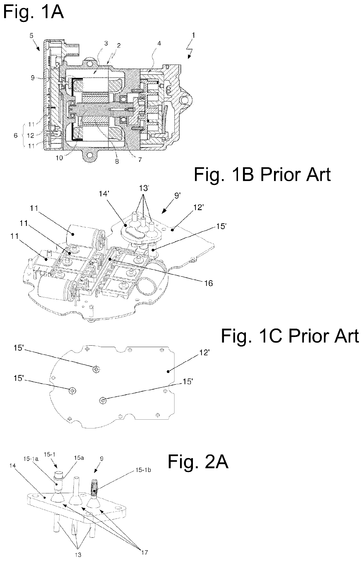
[0067]FIG. 1A shows an electrically driven compressor 1 of a vaporous fluid, specifically for a motor vehicle air-conditioning system for conveying refrigerant through a refrigerant circuit, with an electric motor 3 arranged in a housing 2, as a device 3 for driving a compressing mechanism 4, and an arrangement of an inverter 5 in a cross-sectional view. The electric motor 3 is supplied with electrical energy via a switching device 6 of the inverter 5.

[0068]The electric motor 3 exhibits a stator 7 with an essentially hollow-cylinder shaped stator core and coils wound on the stator core and a rotor 8 arranged inside the stator 7. The rotor 8 is set in rotary motion when electrical energy is supplied to the coils of the stator 7 via a connection arrangement. The connection arrangement 9 is produced at an end face of the stator 7 and exhibits numerous electrical connections.

[0069]The rotor 8 is arranged coaxially inside the stator 7 and such that it can be rotated around a rotational a...


PUM


Abstract

An arrangement for connecting electrical connections, in particular through a housing, for a device for driving a compressor with a connection arrangement with at least one electrically conductive connecting element and at least one contact device, fixed in a PCB, for mounting the connecting element in an axial direction. The contact device exhibits at least one spring contact element with elastically de-formable lamellar contact springs that are in electrically conductive contact with the connecting element. Furthermore, the invention relates to a method for mounting the arrangement for connecting electrical connections, a device for driving a compressor of a vaporous fluid, in particular an electric motor, with the arrangement and a use of the device according to the invention.

Description

CROSS-REFERENCE TO RELATED PATENT APPLICATIONS[0001]This patent application is a United States nation phase patent application based on PCT / KR2020 / 015535 filed on Nov. 6, 2020, which claims the benefit of German Patent Application No. 10 2019 131 791.6 filed on Nov. 25, 2019, the entire disclosures of which are hereby incorporated herein by reference.TECHNICAL FIELD[0002]The invention relates to an arrangement for connecting electrical connections for a device used to drive a compressor. The invention also relates to a method for mounting the arrangement, and a device used to drive a compressor, in particular an electric motor to compress a vaporous fluid, in particular a refrigerant. The compressor can be used in a refrigerant circuit of a motor vehicle air-conditioning system.BACKGROUND ART[0003]Compressors for mobile applications known from prior art, in particular for motor vehicle air-conditioning systems, and used to convey refrigerant through a refrigerant circuit, which are ...

Claims


Application Information

Patent Timeline
IPC IPC(8): H01R13/17H01R12/71H01R43/02H02K5/22B60H1/00
CPCH01R13/17H01R12/71H01R43/0256H02K5/225B60H1/00814H01R12/58H01R13/2407H01R12/50H01R43/007H01R13/639H05K7/2039H02K11/0094H02K11/30H02K3/50F04B35/04F04B53/00C23F13/16E21B43/12E21B43/26C23F2213/30H01R4/02H01R13/04H01R13/10
Inventor GUNERMANN, BERNDROOKS, ERICGORMANNS, OLIVERGECGEL, SENOL
Owner HANON SYST
Why Eureka
Try Eureka