
Genetic optimization techniques for designing manufacturing facilities

a manufacturing facility and genetic optimization technology, applied in the field of computer science and computeraided design, can solve the problems of not incorporating functionality to automatically analyze different designs of manufacturing facilities, conventional cad software does not incorporate functionality to analyze a given design of manufacturing facilities, and the overall process of designing a manufacturing facility using conventional cad software and spreadsheets is typically quite tedious and time-consuming, so as to increase the likelihood of generating and identifying an optimized design for a complex manufacturing facility or other structur

Pending Publication Date: 2022-10-06
AUTODESK INC
View PDF0 Cites 0 Cited by
  • Summary
  • Abstract
  • Description
  • Claims
  • Application Information

AI Technical Summary

Benefits of technology

The patent describes techniques that can be added to a CAD application to accurately calculate travel distances and account for congestion in manufacturing facilities. This results in a more precise design process and increases the likelihood of identifying an optimal design. Overall, these techniques improve the efficiency of designing complex manufacturing facilities.

Problems solved by technology

One drawback of using convention CAD software to design a manufacturing facility is that conventional CAD software does not incorporate functionality to automatically analyze different designs of a manufacturing facility.
For example, conventional CAD software does not incorporate functionality to analyze a given design of a manufacturing facility based on shortest distances that different manufacturing components travel from loading docks at which those components are unloaded from trucks or other vehicles to workstations for assembly or processing and then back to loading docks at which the assembled or processed components are loaded onto trucks or other vehicles.
Accordingly, the overall process of designing a manufacturing facility using conventional CAD software and spreadsheets is typically quite tedious and time consuming.
Further, conventional spreadsheets do not incorporate functionality to accurately compute the shortest distances that components travel within a manufacturing facility.
However, such an approximation may be inaccurate if the manufacturing component is able to traverse the manufacturing facility without actually reaching any corners of the manufacturing facility.
Because the overall process of designing a manufacturing facility using spreadsheets can be inaccurate, generating and identifying designs that are associated with shortest travel distances for different manufacturing components can be quite difficult.
In addition, convention CAD software does not incorporate functionality to analyze designs of a manufacturing facility with respect to levels of congestion when multiple components simultaneously transit a manufacturing facility.
Accordingly, the design process may not account for certain criteria relevant to generating and identifying optimized designs for the manufacturing facility.
Given the above deficiencies of conventional CAD software and design approaches, only a limited number of designs for a manufacturing facility can be generated and considered during a typical design process relative to an overall design space where factors such as shortest distance and congestion are relevant when determining the relative efficiencies of different geometries associated with the various aspects of the manufacturing facility and / or different assignments of manufacturing components to loading docks.
Consequently, very few, if any of the designs for manufacturing facilities generated using conventional CAD software are properly optimized.
In addition, when the disclosed techniques are incorporated into a CAD application, the CAD application also can automatically account for levels of congestion within a manufacturing facility during operation, which is a factor that usually cannot be considered when generating designs using conventional CAD software.

Method used


Image

  • Genetic optimization techniques for designing manufacturing facilities
  • Genetic optimization techniques for designing manufacturing facilities
  • Genetic optimization techniques for designing manufacturing facilities

Examples


Embodiment Construction

[0023]In the following description, numerous specific details are set forth to provide a more thorough understanding of the present disclosure. However, it will be apparent to one of skilled in the art that the present disclosure may be practiced without one or more of these specific details.

System Overview

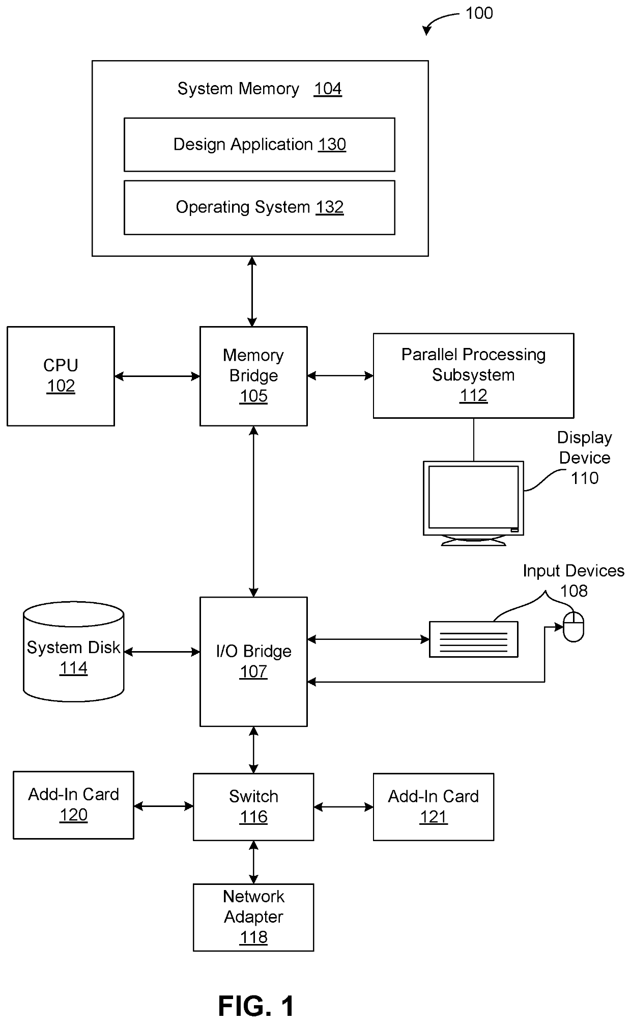
[0024]FIG. 1 is a conceptual illustration of a system 100 configured to implement one or more aspects of the various embodiments. In various implementations, system 100 may be an augmented reality, virtual reality, or mixed reality system or device, a personal computer, video game console, personal digital assistant, mobile phone, mobile device or any other device suitable for practicing one or more embodiments of the present invention.

[0025]As shown, system 100 includes a central processing unit (CPU) 102 and a system memory 104 communicating via a bus path that may include a memory bridge 105. The CPU 102 includes one or more processing cores, and, in operation, the CPU 102 is t...


PUM


Abstract

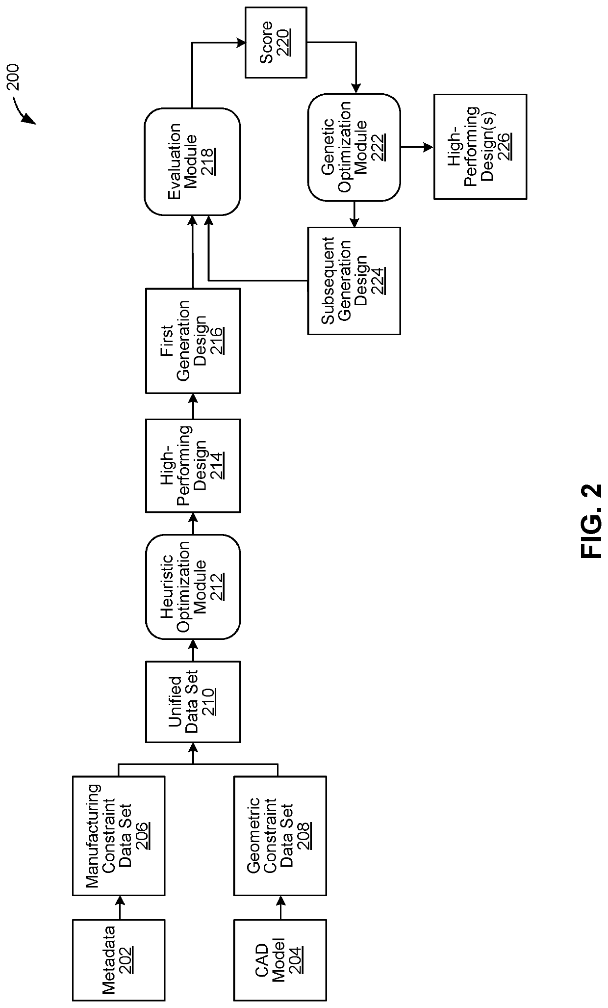
Techniques are disclosed for designing manufacturing facilities. A design application imports a computer-aided design (CAD) model and metadata associated with a manufacturing facility to generate a data set that specifies geometric and manufacturing constraints of the manufacturing facility. The design application performs optimization operations based on the data set to identify one or more high-performing designs that assign components to docks in the manufacturing facility. The optimization operations can include genetic optimization operations that generate multiple generations of designs, each of which is evaluated based on a travel distance, congestion, and number of turns associated with paths traversed by components for the design.

Description

BACKGROUNDField of the Disclosure[0001]Embodiments of the present disclosure relate generally to computer science and computer-aided design and, more specifically, to genetic optimization techniques for designing manufacturing facilities.Description of the Related Art[0002]Computer-aided design, among other things, utilizes computers to aid in creating, analyzing, modifying, and / or optimizing structural designs. In this regard, computer-aided design (CAD) applications are oftentimes used to design the layouts of manufacturing facilities for companies operating in a multitude of various industries.[0003]In the context of manufacturing facilities, a typical facility includes a number of workstations at which manufacturing components are assembled or otherwise processed. A typical facility also has a number of loading docks that are used to unload those components from trucks or other vehicles for assembly or processing and then are used to load those components back onto trucks or veh...

Claims


Application Information

Patent Timeline
IPC IPC(8): G06F30/17G06F30/13G06F30/20
CPCG06F30/17G06F30/13G06F30/20G06F2119/12Y02P90/02
Inventor LAU, DAMONBENJAMIN, DAVIDSTODDART, JAMESVILLAGGI, LORENZOZHAO, DALE
Owner AUTODESK INC
Learn More