Airfoil system with embedded electric device

Pending Publication Date: 2022-10-27
ROHR INC
View PDF3 Cites 0 Cited by
  • Summary
  • Abstract
  • Description
  • Claims
  • Application Information

AI Technical Summary

Problems solved by technology

While mounting the antenna on the exterior of the airplane may provide a substantially unobstructed signal path between the exposed antenna and the remote entity, exposure of the antenna increases airplane drag.
While mounting the antenna within the interior of the airplane reduces airplane drag, a structure (e.g., skin, frame, etc.) surrounding the antenna may interfere

Method used


Image

  • Airfoil system with embedded electric device
  • Airfoil system with embedded electric device
  • Airfoil system with embedded electric device

Examples


Example

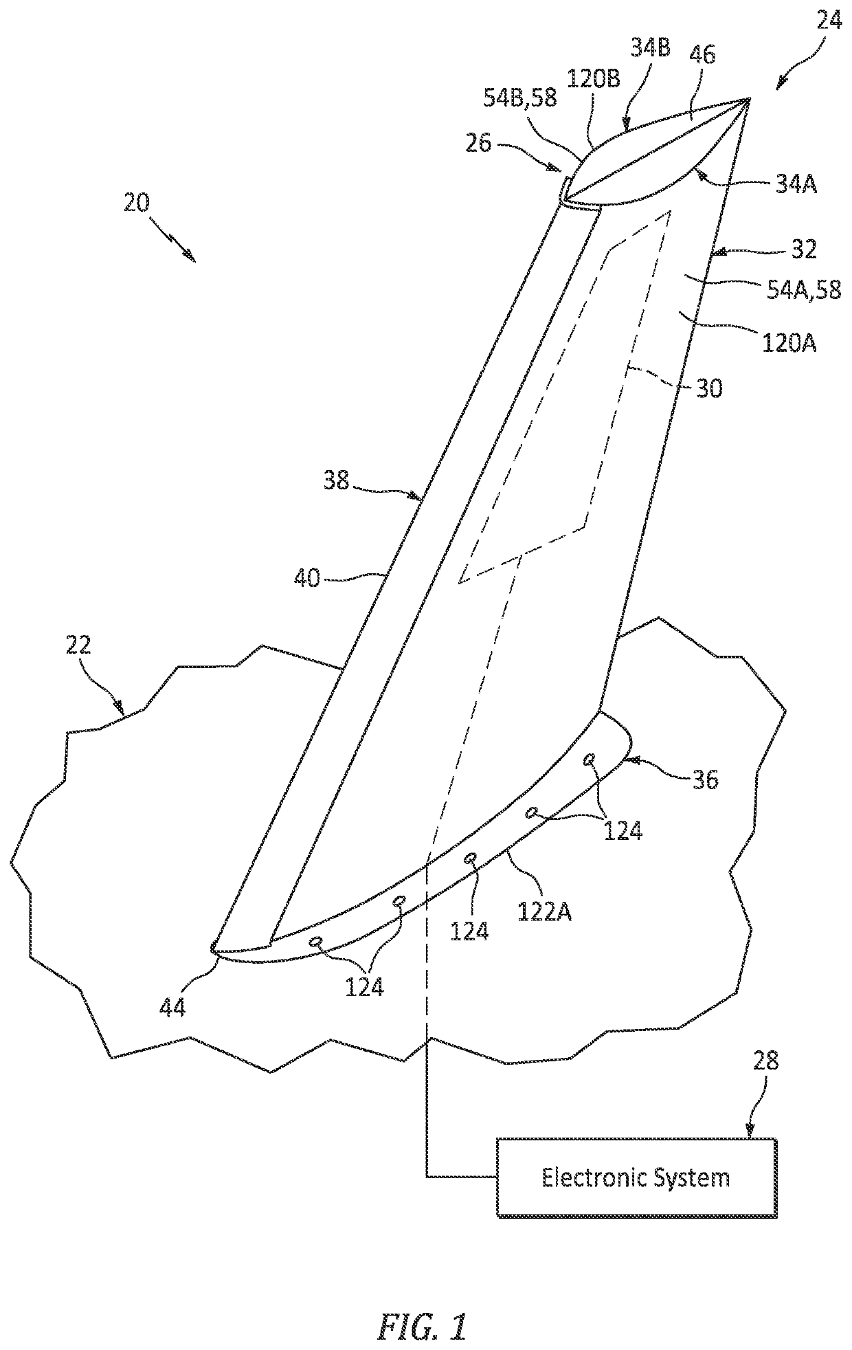
[0041]FIG. 1 illustrates a portion of an assembly 20 for an aircraft. Herein, the term “aircraft” may generally describe any mobile device which travels through at least air and / or space. The aircraft, for example, may be configured as an airplane, a helicopter, a spacecraft, a drone (e.g., an unmanned aerial vehicle (UAV)) or a projectile such as, but not limited to, a rocket. The present disclosure, however, is not limited to the foregoing exemplary aircraft configurations.

[0042]The aircraft assembly 20 of FIG. 1 includes a base 22 and an airfoil system 24. The aircraft assembly base 22 may be any portion of the aircraft to which the airfoil system 24 may be mounted. The aircraft assembly base 22, for example, may be configured as an exterior skin or other exterior structure of: an aircraft fuselage, an aircraft tail assembly, an aircraft wing, an engine pylon or a nacelle housing an aircraft engine. The present disclosure, however, is not limited to the foregoing exemplary aircra...


PUM


Abstract

An airfoil system is provided that includes an airfoil and an electric device. The airfoil includes a first exterior surface, a second exterior surface, a first airfoil segment and a second airfoil segment attached to the first airfoil segment. The airfoil extends widthwise between the first exterior surface and the second exterior surface. The first airfoil segment forms the first exterior surface. The second airfoil segment forms the second exterior surface. The electric device is embedded within the airfoil between the first airfoil segment and the second airfoil segment.

Description

BACKGROUND1. Technical Field[0001]This disclosure relates generally to an aircraft and, more particularly, to systems and devices for arranging one or more electric devices on an exterior of the aircraft.2. Background Information[0002]A modern aircraft such as an airplane includes a communication system. This communication system may include an antenna for relaying signals between the airplane and another remote entity; e.g., another airplane, ground control, satellites, etc. This antenna may be mounted on an exterior of the airplane or within an interior of the airplane; e.g., beneath a skin of an airplane fuselage or an airplane wing. While mounting the antenna on the exterior of the airplane may provide a substantially unobstructed signal path between the exposed antenna and the remote entity, exposure of the antenna increases airplane drag. While mounting the antenna within the interior of the airplane reduces airplane drag, a structure (e.g., skin, frame, etc.) surrounding the ...

Claims


Application Information

Patent Timeline
IPC IPC(8): B64C3/20B64C3/26B64F5/10
CPCB64C3/20B64C3/26B64F5/10B64C5/06B64D43/00H01Q1/287B29D99/0028B29C70/88B29C70/70
Inventor LACKO, ANTHONY
Owner ROHR INC
Why Eureka
Try Eureka