
Pollutant Capturer and Mobilizer

Pending Publication Date: 2022-11-03
SALEHPOOR KARIM
View PDF8 Cites 0 Cited by
  • Summary
  • Abstract
  • Description
  • Claims
  • Application Information

AI Technical Summary

Benefits of technology

Effectively captures a wide range of pollutants with minimal energy consumption and CO2 production, enabling net reduction in atmospheric CO2 levels and addressing health, environmental, and economic impacts of pollution.

Problems solved by technology

Increase in concentration of atmospheric carbon dioxide is known to be a contributor to global warming, climate change and extreme weather conditions, drought, polar ice melt and rise in ocean level which threatens human life on many islands.
The secondary recovery of petroleum, described above, indicates that the use of carbon dioxide for injection into geological reservoirs or absorption of carbon dioxide by hydrocarbons have been discussed in the past, however, only as a means of improving oil recovery from geologic hydrocarbon reservoirs and with no considerations regarding achieving a net carbon dioxide reduction as a result of preparing the injection fluid or the injection process itself.
The secondary recovery of oil from a subterranean formation, described above, indicates that the use of carbon dioxide for injection into geological reservoirs has been discussed in the past, however, only as a means of improving oil recovery from geologic hydrocarbon reservoirs and with no considerations regarding achieving a net carbon dioxide reduction as a result of the injection process itself.
The combination methods involving the making of gaseous carbon dioxide and its use in crude oil recovery, described above, indicates that the use of carbon dioxide for injection into geological hydrocarbon reservoirs or absorption of carbon dioxide by hydrocarbons and the reduction of the viscosity of the hydrocarbon oil as a result of absorbing carbon dioxide have been discussed in the past, however, only as a means of improving oil recovery from geologic hydrocarbon reservoirs and with no considerations regarding achieving a net carbon dioxide reduction associate with the injection process itself.
The method for enhanced oil recovery, described above, indicates that the use of carbon dioxide for injection into geological hydrocarbon reservoirs for improving oil recovery or mixing carbon dioxide with oil have been discussed in the past, however, only as a means of improving oil recovery from geologic hydrocarbon reservoirs and with no considerations regarding achieving a net carbon dioxide reduction associate with all aspects of the process of injecting carbon dioxide into the oil reservoirs.
The carbon dioxide stimulated oil recovery process, described above, indicates that the use of carbon dioxide for injection into geological hydrocarbon reservoirs for improving oil recovery or dissolution of carbon dioxide in the crude oil have been discussed in the past, however, only as means of improving oil recovery from geologic hydrocarbon reservoirs and with no considerations regarding achieving a net carbon dioxide reduction associate with all aspects of the process of injecting carbon dioxide into the oil reservoirs.
The electrostatic air cleaner, described above, utilizes multiple electrical components, and therefore, it requires use of significant amount of electricity.
Therefore, even though the electrostatic air cleaner might be capable to clean air from particulates to some extent, its operation is still associated with polluting the atmospheric air with carbon dioxide.
The exhaust air cleaning apparatus and image forming apparatus, described above, is intended for use with an image forming apparatus such as a copier, a printer, or a facsimile machine that generates various by-products during image formation; such apparatus is not capable of removing particulate polluting substances from atmospheric air or from a conduit that carries combustion products.
The apparatus is not also capable of removing carbon dioxide from the atmospheric air or the combustion products.
Therefore, even though the ion filtration air cleaner might be capable to clean air from particulates to some extent, its operation is still associated with polluting the atmospheric air with carbon dioxide.
Therefore, even though the dust collector, dust collection system, and dust collection method might be capable to clean air from particulates to some extent, its operation requires the use of spraying water and is still associated with polluting the atmospheric air with significant amount of carbon dioxide.
Therefore, even though the air cleaning device might capture charged particulates to some extent, its use is associated with a significant amount of electricity and thus the function of the air cleaning device contributes to increasing the level of atmospheric carbon dioxide since a large portion of electric power is still generated by burning fossil fuels.
However, all of these methods and devices have one or multiple deficiencies with regards to utilizing fans or other compression equipment thus producing CO2 associated with implementation of the process itself, having potential for both small scale and large scale applications, utilizing simple process or equipment or design or methodology, capability of capturing a diverse types of polluting substances, the amount of electrical or mechanical or thermal energy required for the device to function, capability to capture CO2 from a variety of sources such as CO2 in combustion products that flows in a chimney or stack or vehicle's exhaust pipe, CO2 produced within buildings or plants or facilities as well as capturing the atmospheric CO2, capability to be incorporated in existing buildings or plants or facilities with minimum required remedial work or changes in the design of the existing buildings or plants or facilities, and capability of capturing particulate polluting substances as well as CO2 and other gaseous polluting substances from a body of polluted gaseous substance.
Also, the methods and devices that are reviled in the prior art do not offer a possibility for individual members of the public communities to contribute to the capturing or storing activities with regards to the CO2 and thus it is unlikely that such methods or devices can lead to achieving positive results in capturing or storing CO2 with no net reduction of CO2 in the process.

Method used


Image

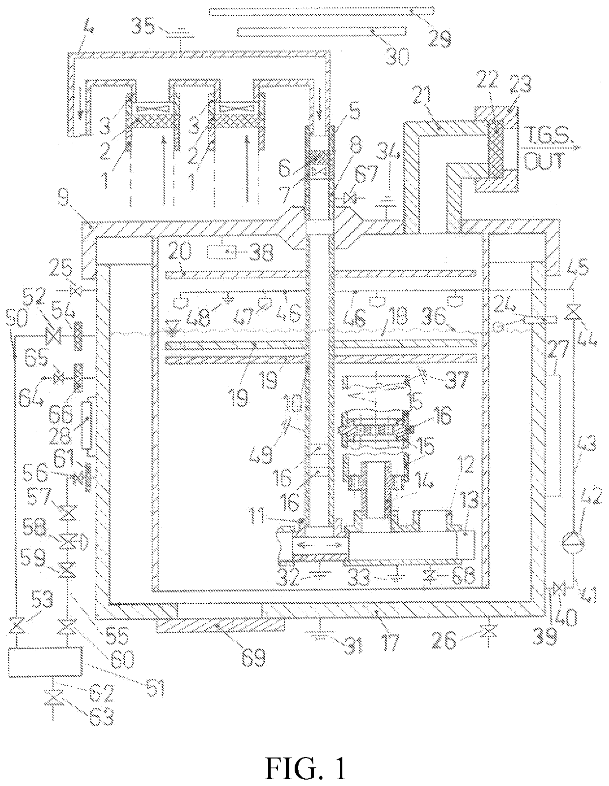
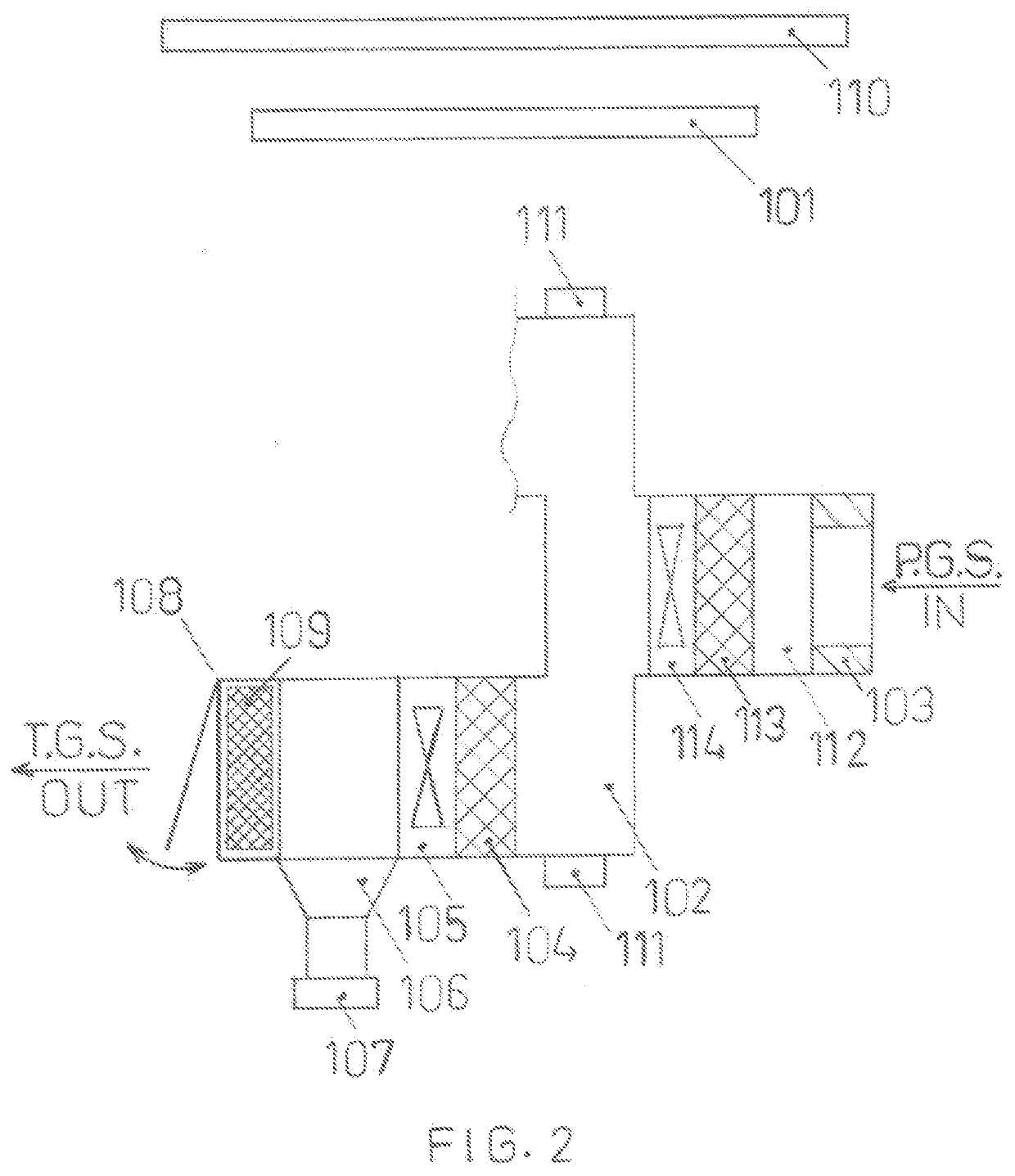
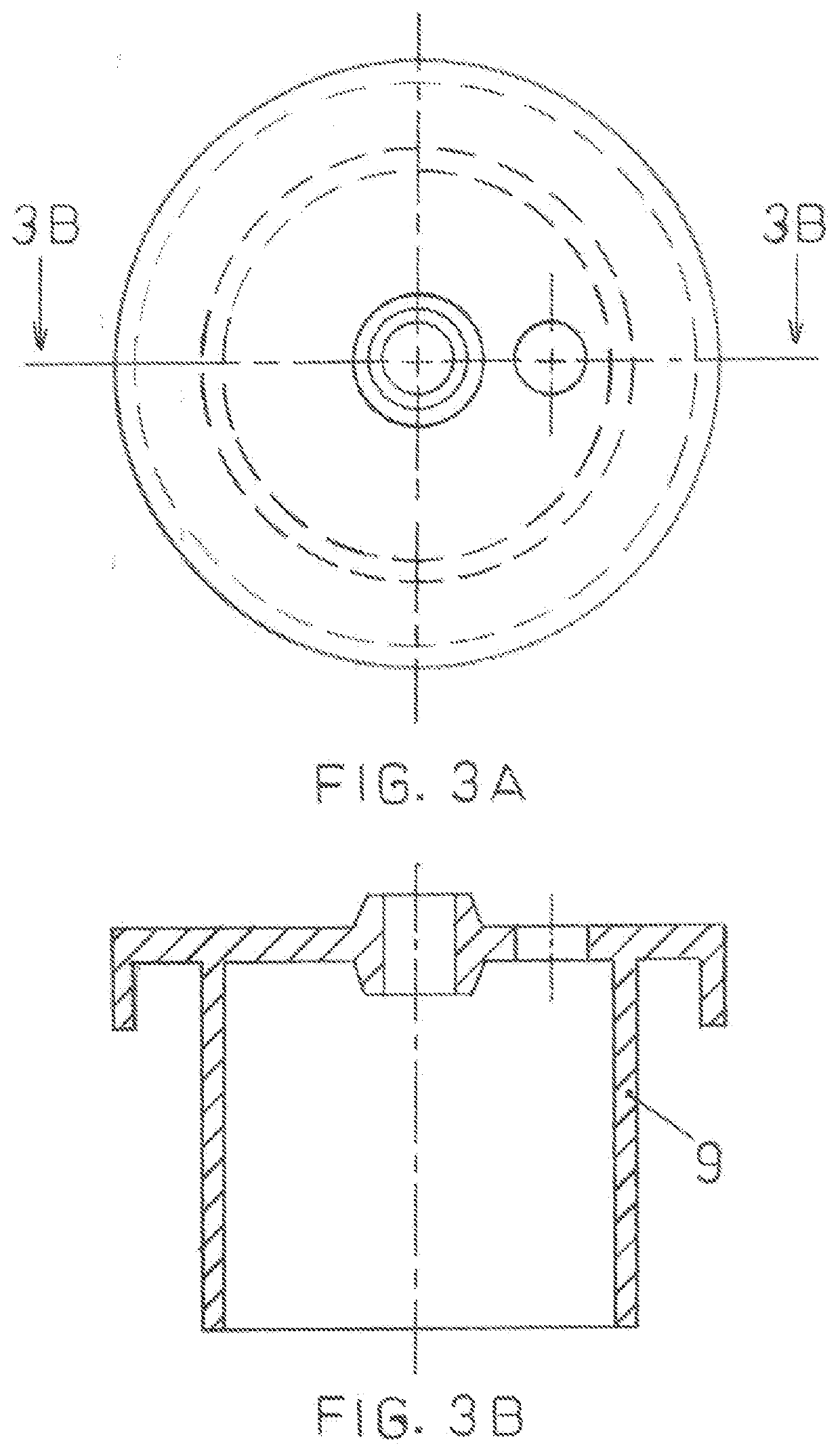
  • Pollutant Capturer and Mobilizer
  • Pollutant Capturer and Mobilizer
  • Pollutant Capturer and Mobilizer

Examples


Embodiment Construction

1. Definitions

[0074]Pollutant or polluting substance as used herein shall mean any type of airborne gas or water vapor or moisture or particulate substance such as pollen, fumes, fog, smog, ash, soot, dust, sand, smoke, combustion products, carbon dioxide, any other gases or airborne particulate substances, or extreme thermal energy that is contained in a body of air or gaseous substance and can have undesired impact on the environment or surroundings or human health.

[0075]Polluted gaseous substance as used herein shall mean a gaseous substance that contains one or multiple types of polluting substances.

[0076]Pollutant Capturing Component (or P.C.C.) as used herein shall mean any type of manufactured, or synthetic, or naturally occurring substance, or any combination of the above said substances, that can capture and thus remove at least one type of polluting substances from a body of polluted gaseous substance by means of dissolving, or by means of absorbing, or by means of formati...


PUM

PropertyMeasurementUnit
critical temperatureaaaaaaaaaa
pressureaaaaaaaaaa
concentrationaaaaaaaaaa

Abstract

Disclosed are a pollutant capturer and mobilizer and method of mobilizing a polluted gaseous substance from one location towards another location and capturing one or multiple types of polluting substances, such as CO2, from an atmospheric body of polluted gaseous substance or from exhaust of vehicles, chimneys, or stacks and thereby combat the negative health, environmental, and economic impacts of the of the polluting substances on communities. Wet or dry embodiments of the pollutant capturer and mobilizer utilize wet or dry pollutant capturing components, respectively, to capture one or multiple types of polluting substances from a body of polluted gaseous substance. Flow-establishing devices can be used to set the body of polluted gaseous substance in motion through the pollutant capturing component. The pollutant capturer and mobilizer may also be mounted on any type of vehicle, with or without using flow-establishing devices.

Description

CROSS-REFERENCE TO RELATED APPLICATION(S)[0001]This application is a divisional of U.S. patent application Ser. No. 16 / 298,730, filed Mar. 11, 2019, pending, incorporated herein by reference.BACKGROUND OF THE INVENTION1. Field of the Invention[0002]The present invention relates to a pollutant capturer and mobilizer for moving a body of polluted gaseous substance from one location towards another location and remove CO2 or other undesired gases, as well as smog, fog, water vapor, any type of airborne pollutants including pollen, fumes, ash, smoke, soot, dust, combustion products, sand, and any other airborne particulate substances from the body of polluted gaseous substance such as air in buildings, atmospheric air, atmospheric air in a building blow-down demolishing site, atmospheric air nearby active volcanoes and wild fires, exhaust from any type of vehicles, as well as exhaust from vehicles' exhaust pipe and chimneys or stacks of buildings, industrial plants, and facilities in an...

Claims


Application Information

Patent Timeline
Patent Type & Authority Applications(United States)
IPC IPC(8): B01D47/02B01D46/00B01D46/42B01D53/14B01D53/18A01G15/00B01D47/06F01N3/04F23J15/04B01D46/58B01D46/62B01D50/60E03B3/28
CPCB01D47/021B01D46/0031B01D46/0087B01D46/4218B01D46/4254B01D53/1475B01D53/145B01D53/18A01G15/00B01D47/06B01D53/14F01N3/04B01D47/02F23J15/04B01D46/58B01D46/645B01D50/60E03B3/28B01D2252/20B01D2279/30B01D2279/40B01D2252/103Y02C20/40B01D2258/06Y02P60/20Y02P70/10Y02E20/32B01D46/12B01D45/18
Inventor SALEHPOOR, KARIM
Owner SALEHPOOR KARIM
Learn More