Dual-band multimode antenna feed

a multi-mode, antenna technology, applied in the direction of antennas, waveguide horns, electrical equipment, etc., can solve the problems of difficult to implement dual-band operation in such a feed, antenna bulky, fragile support struts,

Pending Publication Date: 2022-11-03
SAAB AB
View PDF0 Cites 0 Cited by
  • Summary
  • Abstract
  • Description
  • Claims
  • Application Information

AI Technical Summary

Problems solved by technology

Such a feed designed for three channels is however a complex device and it is not easy to e.g. implement dual frequency band operation in such a feed.
There are several drawbacks of this solution:The antenna is bu

Method used


Image

  • Dual-band multimode antenna feed
  • Dual-band multimode antenna feed
  • Dual-band multimode antenna feed

Examples


Embodiment Construction

[0051]In the description, references to the E-plane and H-plane are made. The E-plane is the plane along which the electric field has its polarisation. The H-plane is the plane along which the magnetic field has its polarisation.

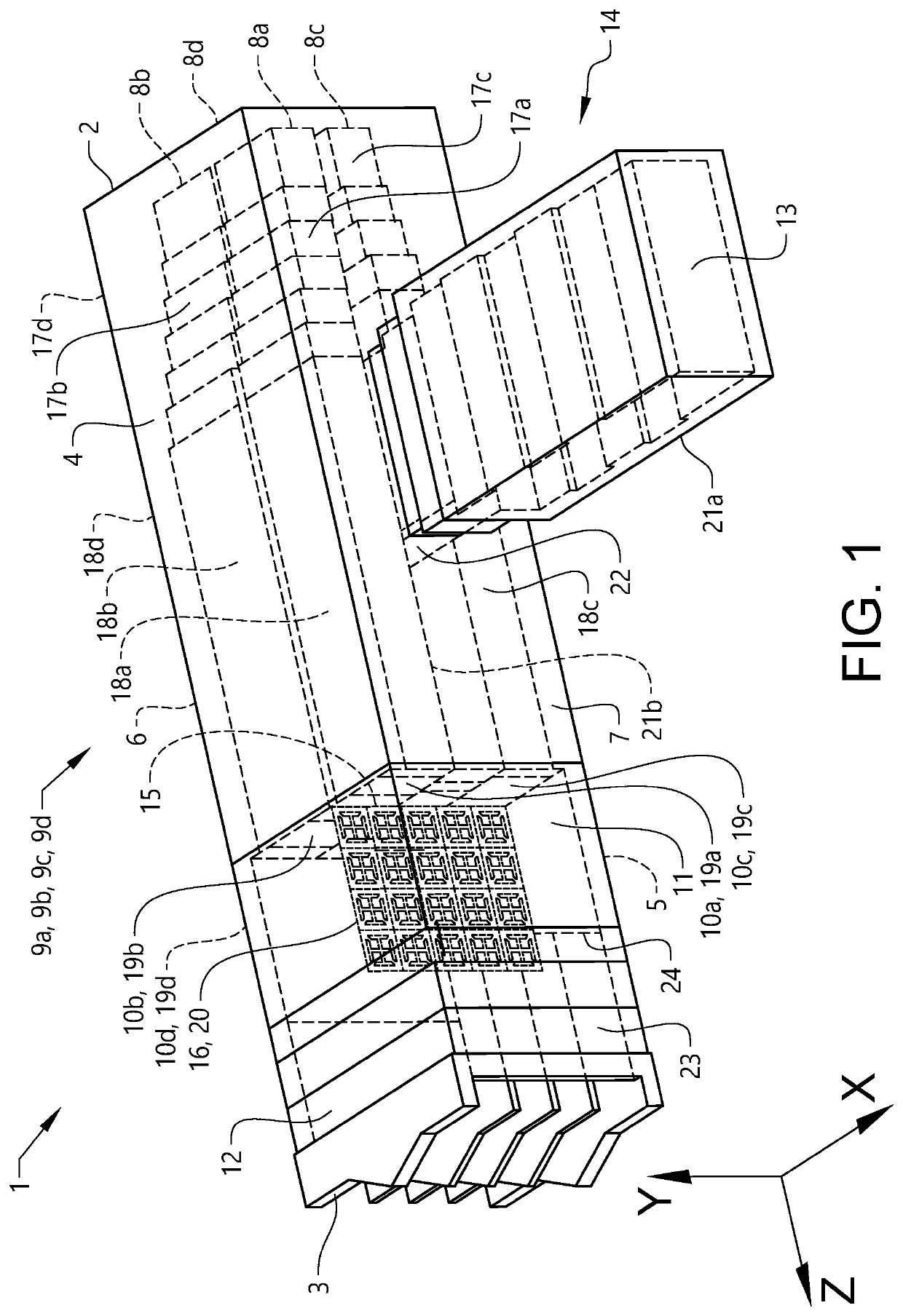
[0052]FIG. 1 schematically shows a perspective view of an antenna feed 1 according to the disclosure. The antenna feed 1 is a dual-band multimode antenna feed for a high-frequency band and a low-frequency band. The antenna feed 1 has a length extension along a z-axis, a height extension along a y-axis and a width extension along an x-axis. The antenna feed 1 has a rear end 2, a front end 3, an upper side 4, a lower side 5, a right side 6 and a left side 7. The axes are intended to be used to describe the positions of the antenna feed's 1 different features relative each other and should not be seen as an indication of how the antenna feed 1 is arranged in use. The interior parts of the antenna feed 1 are illustrated by dashed outlines.

[0053]The antenna feed ...


PUM


Abstract

Provided is a dual-band multimode antenna feed for a high-frequency band and a low-frequency band. The feed includes four high-frequency waveguide ports, where each high-frequency waveguide port is connected to a respective high-frequency input/output waveguide. Each high-frequency input/output waveguide includes a high-frequency waveguide aperture facing a first section for mixing electromagnetic modes in the E-plane. The first section is connected to a second section for mixing electromagnetic modes in the H-plane. The feed further includes a low-frequency waveguide port connected to a low-frequency input/output waveguide. A filter is arranged inside the first section to be transparent for plane wave modes exhibited at lower frequencies and reflecting for plane wave modes exhibited at higher frequencies.

Description

TECHNICAL FIELD[0001]The application relates to a dual-band multimode antenna feed for a high-frequency band and a low-frequency band. The feed comprises four high-frequency waveguide ports, each high-frequency waveguide port being connected to a respective high-frequency input / output waveguide. Each high-frequency input / output waveguide has a high-frequency waveguide aperture facing a first section for mixing electromagnetic modes in the E-plane. The first section is connected to a second section for mixing electromagnetic modes in the H-plane. The application also relates to providing an antenna feed.BACKGROUND ART[0002]So called monopulse-techniques are used in many types of antennas where accurate position estimation of objects is required. Position estimation is obtained by generation of so called sum- and difference radiation patterns simultaneously in different antenna channels. Thus the term mono-pulse; in theory, the position of an object can be determined by one radar-puls...

Claims


Application Information

Patent Timeline
IPC IPC(8): H01Q25/04H01Q15/22H01P1/213H01P1/16H01Q13/02
CPCH01Q25/04H01Q15/22H01P1/2131H01P1/16H01Q13/025H01Q15/248H01Q19/195H01Q5/55H01Q5/47
Inventor FORSLUND, OLA
Owner SAAB AB
Why Eureka
Try Eureka