Hydraulically-operated bicycle shifting system with positive pressure actuation

a technology of positive pressure and shifting system, applied in the field of bicycles, can solve the problems of affecting the precision of the derailleur, difficult shifting of the derailleur, and the work of various contaminants in the derailleur

Inactive Publication Date: 2000-01-11
PATTERSON RICHARD A
View PDF60 Cites 74 Cited by
  • Summary
  • Abstract
  • Description
  • Claims
  • Application Information

AI Technical Summary

Problems solved by technology

Unfortunately, the front and rear chain shifting systems have remained essentially unchanged, and still use mechanical cables to control the chain guiding mechanisms.
However, when mountain bikes are used in the dusty, wet, and muddy conditions found on rugged and primitive roads and trails, various contaminants work their way into the derailleur's pivots and open linkages as well as into and under tension control cables.
Such contamination makes the derailleurs difficult to shift, adversely affects their precision in shifting, and also makes them wear out very quickly.
Under extremely harsh operating conditions, existing mechanical derailleurs will fail, making it impossible for the cyclist to change drive ratios.
Rubber covers or boots provide some protection for the parallel linkages on the front and rear derailleur mechanisms, but these covers are not waterproof, and mud and water can still enter the mechanisms.
However, dirt can still enter these control cables and cause the cables to stick or bind inside their flexible guide housings.
While this design avoids the problems associated with contamination of tension cables and related components, it presents several other problems.
The first problem relates to the limited amount of force that can be applied with this design.
However, the partial vacuum also acts upon the soft side walls of the bellows, tending to cave them inward.
This e

Method used


Image

  • Hydraulically-operated bicycle shifting system with positive pressure actuation
  • Hydraulically-operated bicycle shifting system with positive pressure actuation
  • Hydraulically-operated bicycle shifting system with positive pressure actuation

Examples


Embodiment Construction

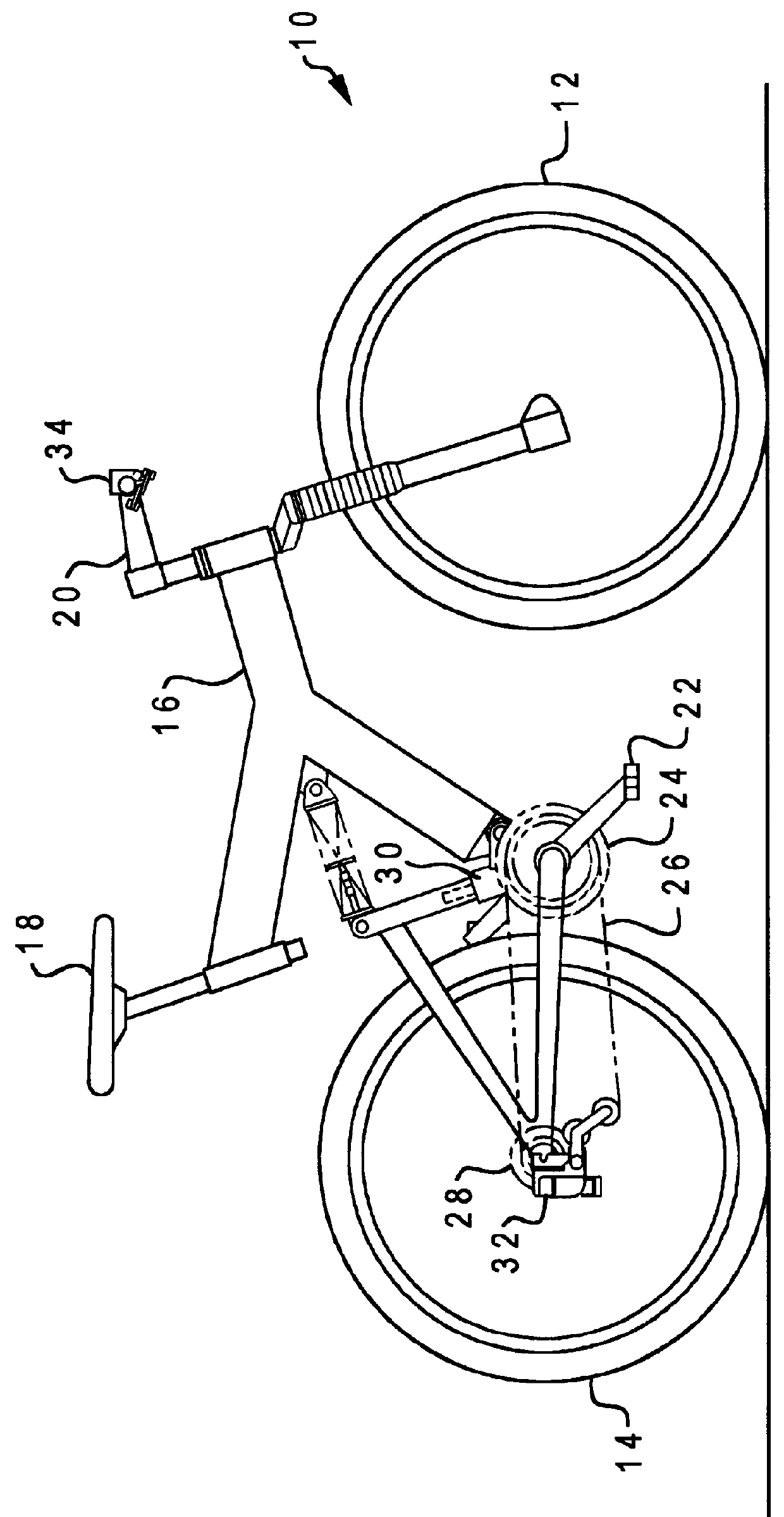
With reference now to the figures, and in particular with reference to FIG. 1, there is depicted one embodiment 10 of a bicycle constructed in accordance with the present invention, having a hydraulically-actuated derailleur shifting system. Bicycle 10 has several conventional elements, including front and rear wheels 12 and 14, frame 16, seat 18, handlebars 20, and pedals 22. Pedals 22 are fastened to a pedal crankshaft which in turn is affixed to a cluster 24 of larger diameter sprockets. A drive chain 26 extends between sprocket cluster 24 and a sprocket cassette 28 mounted on the axle of rear wheel 14. Rear wheel sprocket cassette 28 may have a set of, e.g., from five to nine sprockets of slightly different diameters that are mounted to the rear wheel around a ratcheted hub. These sprockets are arranged by size with the smallest being furthest away from the hub and the largest closest to the hub. Two or three larger diameter sprockets may be provided for front wheel sprocket clu...


PUM


Abstract

A family of new bicycle shifting systems incorporate improved derailleur designs that are controlled by sealed hydraulic actuators. The shifting systems (i) a hydraulically-actuated, manually-powered front and rear derailleur shifting system, (ii) a hydraulically-actuated, power-assisted front and rear derailleur shifting system with manual control, and (iii) a hydraulically-actuated, power-assisted front and rear derailleur shifting system in which the shifting sequence for the rear derailleur is controlled automatically by pedal speed. Each of these shifting systems utilize a totally sealed, inclined linear shifting path. Environmental contaminants are prevented from entering any of the critical derailleur or control elements. The linear, inclined shifting path provides precise chain shifting, more uniform chain wrap on the rear bicycle drive sprockets, and lower chain and sprocket wear. Several different shifting control units are disclosed.

Description

1. Field of the InventionThe present invention generally relates to bicycles, and more particularly to hydraulically-operated control systems for bicycles.2. Description of Related ArtBicycles are equipped with multiple gears by operating a drive chain between a cluster of larger diameter sprockets on the pedal crankshaft and a sprocket cassette mounted on the rear wheel axle. A device known as a derailleur is used to position the drive chain on a given sprocket. Existing mechanical derailleur shifting systems usually incorporate four-bar linkage mechanisms that are controlled by tension cables. A rear derailleur is located on the lower slack side of the drive chain at the rear wheel, and a front derailleur is located on the upper tight side of the chain at the sprocket cluster attached to the pedal crankshaft. The shifting control mechanism for mechanical derailleurs can be mounted on the front down tube of the bicycle frame, but most commonly is mounted on the bicycle handle bars....

Claims


Application Information

Patent Timeline
IPC IPC(8): B62M25/00B62M25/08F16H7/08B62M9/122B62M9/1244B62M9/132
CPCB62M9/122B62M9/132B62M25/08F16H2007/0859
Inventor PATTERSON, RICHARD A.
Owner PATTERSON RICHARD A
Why Eureka
Try Eureka