Flywheel with self-expanding hub

a flywheel and hub technology, applied in the direction of mechanical energy handling, vibration suppression adjustment, mechanical apparatus, etc., can solve the problems of high load on components such as shaft bearings, inability to produce a high energy storage flywheel that is small and light enough to satisfy, and attenuating potentially destructive resonances

Inactive Publication Date: 2000-01-18
OPTIMAL ENERGY SYST
View PDF10 Cites 33 Cited by
  • Summary
  • Abstract
  • Description
  • Claims
  • Application Information

AI Technical Summary

Problems solved by technology

Flywheel developers have been unable to produce a high energy storing flywheel that is small and light enough to satisfy the demands of the highest potential markets because of the stresses encountered at high speeds.
In addition, flywheel imbalances, caused by component misalignment and eccentricity, can attenuate potentially destructive resonances and place high loads on components such as shaft bearings.
Some single core design hubs can be found but are deficient in that they exhibit axial motions parallel to the shaft that are much larger in magnitude than the expansion matching achieved by the design.
As a result, conical disks have not been widely utilized in high speed flywheel designs.
This high flexibility coupled with the low mass of flexure hub approaches make these design approaches incapable of producing "compression locking" at the hub to rotor interface.
Consequently, these design approaches fail to address the catastrophic radial tensile stresses that are the limiting feature of all filament wound composite rotor designs.
Though graphite composite flywheels have high strength, even higher than the most sophisticated high alloy steels, the composite matrix that binds the fibers together is relatively weak.
This destroys the flywheel before the flywheel can reach high speeds.
This is not the preferred method of fabrication due to the lack of precision control on uniformity and concentricity.
The resulting hub design, based upon engineering analysis and computer simulation, does not allow the fiber matrix of the rotor to pull apart when the flywheel spins at very high speeds.
This reduces vibration in the rotor which, in turn, reduces the reaction loadings which impair operational life such as shaft bearing wear and hub fatigue.
Typically with other "flexure hub" approaches, increase in resistance to angular nutation can be achieved only at a significant loss in centrifugal expansion capability of the hub and creates catastrophic radial stresses at the hub to rotor interface when placed in high speed applications.
The tunability aspect cannot be accomplished in other "flexure" hub approaches.
Consequently, for very large diameter rotor to hub interfaces, these hub devices are impractical to package.
Carbon fiber and epoxy matrix composites also exhibit good strength-to-weight ratios but may be less desirable because of greater out-gasing.

Method used


Image

  • Flywheel with self-expanding hub
  • Flywheel with self-expanding hub
  • Flywheel with self-expanding hub

Examples


Embodiment Construction

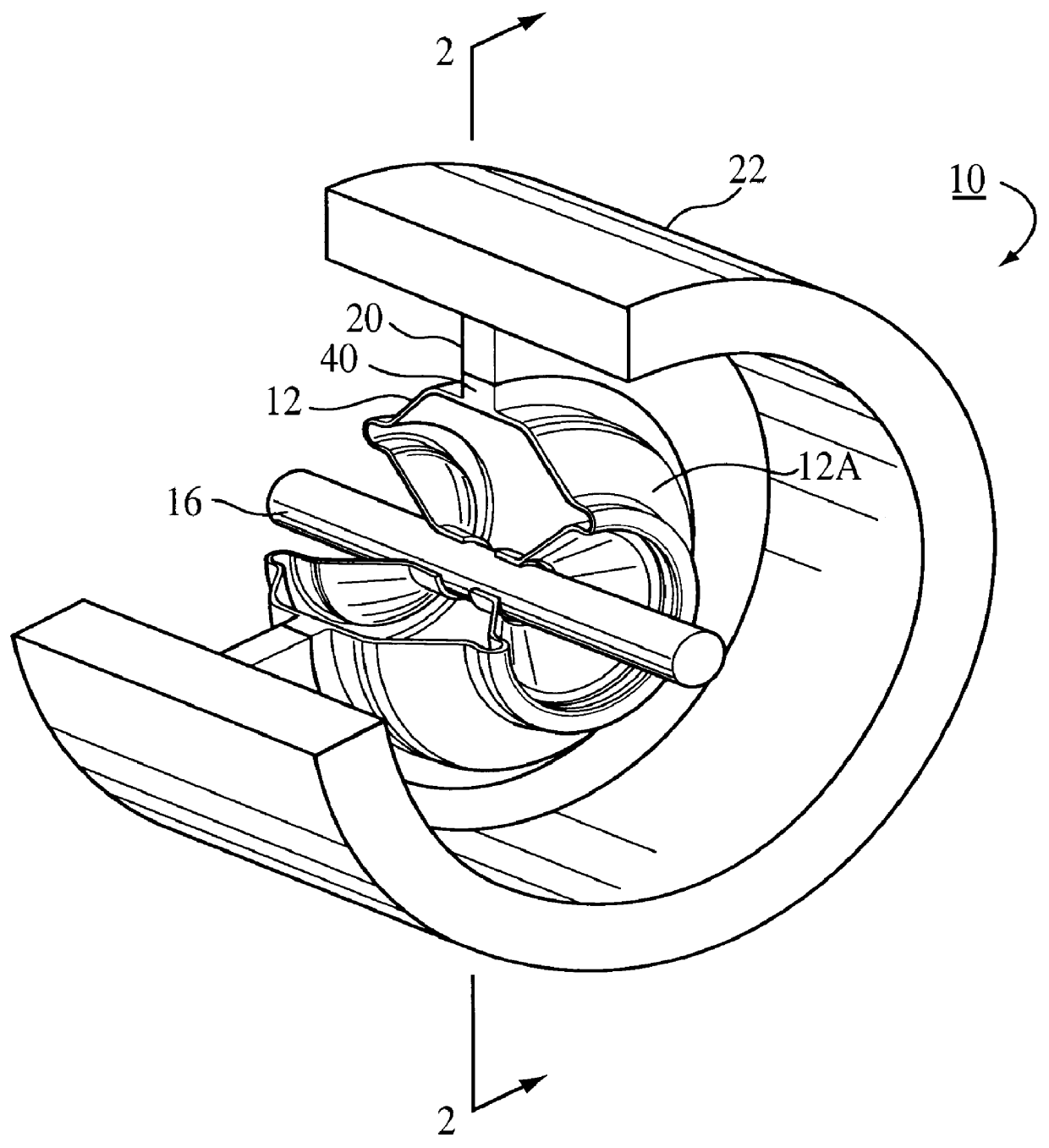
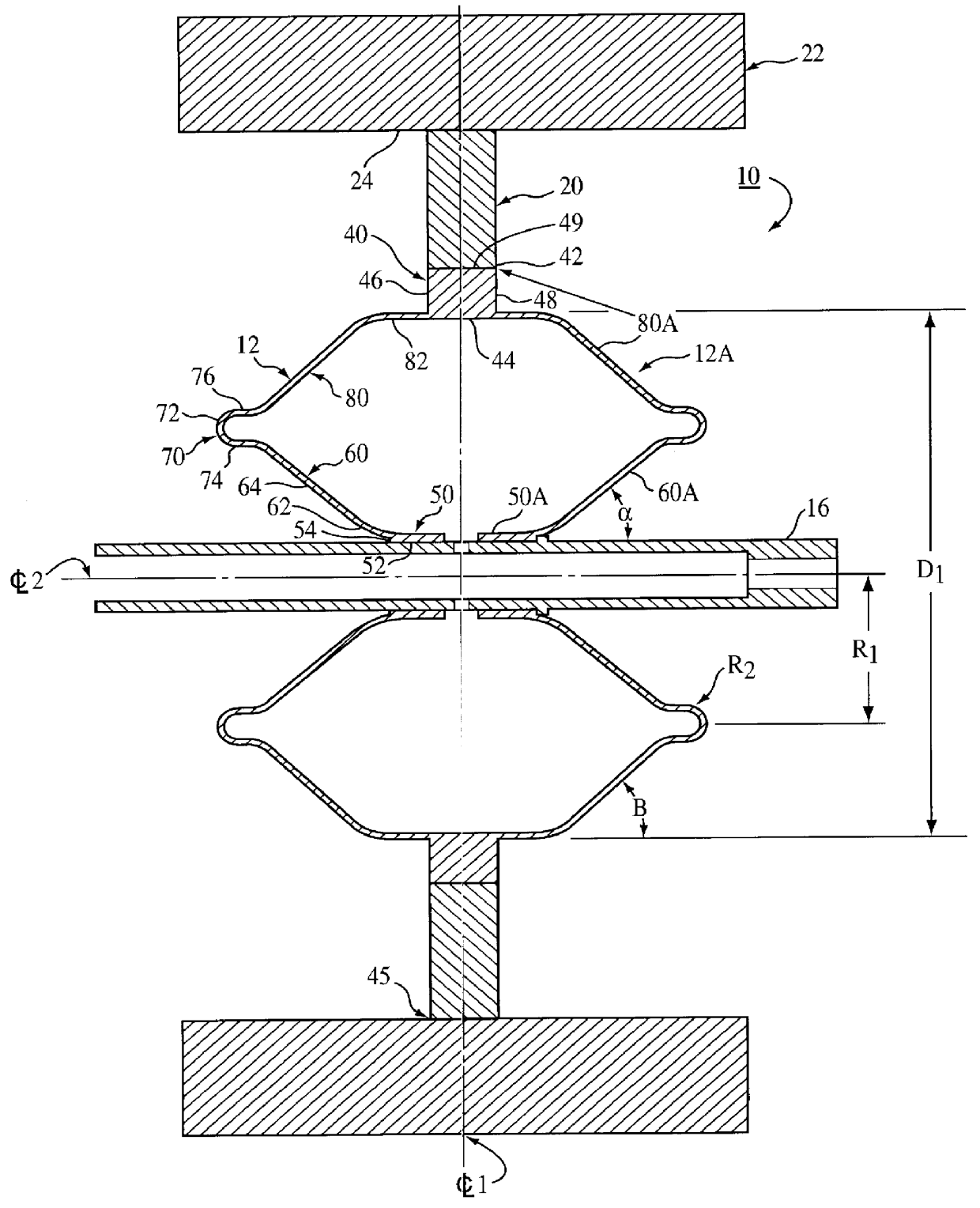
In order to prove the effectiveness of the design, computer analysis was performed on a flywheel design constructed as shown in FIGS. 1 and 2. The hub was mounted on a 4130 hollow steel shaft having an outer diameter of 0.900" and an inner diameter of 0.620". Referring to FIG. 2, R.sub.1 =1.981", D.sub.1 =6.885. The axial length of the assembled hub was 5" and the radius R.sub.2 of the tubular rim was 0.20". The material of the hub was a maraging 300 steel with the composition set forth above.

The interface disk was a multiple ply laminate of graphite fiber with an impregnated matrix. The fibers were arranged with an alternating axial and circumferential orientation (0 / 90 lay-up). The interface disk had an inner diameter of 7.9" and an outer diameter of 11.6". The inner diameter of the interface disk bonded to the outer surface of the hoop by epoxy bond.

The outer rotor or rim was 1-1 / 2" thick and an axial width or length of 7.0". It was wound circumferentially with graphite fiber.

The...


PUM


Abstract

A high energy storage flywheel having a rotor and annular disk which are of a composite material. A metal hub is secured to a shaft and joined to the disk at a hoop. The hub has opposite sections which are of a generally double conical shaft. A concentric rim extends around each hub section and upon rotation the hub sections expansivity deform about the rim to apply a compressive force to the disk to maintain a substantially stress free condition at the rotor and disk interface.

Description

1. Field of the InventionThe present invention relates generally to energy storage devices and more particularly to a high energy flywheel design.2. Description of the Prior ArtThe use of flywheels for high energy storage in such applications as hybrid electric vehicles, earth orbiting satellites, military weapons, power utilities, load leveling, space stations and uninterruptable power supplies for computer facilities and electronic manufacturing has long been recognized and new applications are being realized every day. Many of these new applications require greater energy storage capacity and higher energy density (the ratio of the energy stored in a device to the device weight) than is currently available. Flywheel developers have been unable to produce a high energy storing flywheel that is small and light enough to satisfy the demands of the highest potential markets because of the stresses encountered at high speeds. For example, NASA and DOD projects as well as hybrid vehicl...

Claims


Application Information

Patent Timeline
Patent Type & Authority Patents(United States)
IPC IPC(8): F16F15/30F16F15/315
CPCF16F15/3153Y10T74/212Y02E60/16
Inventor SWETT, DWIGHT W.
Owner OPTIMAL ENERGY SYST
Why Eureka
Try Eureka