Methods for forming amorphous ultra-high molecular weight polyalphaolefin drag reducing agents

a drag reducing agent and polyalphaolefin technology, applied in the direction of liquid organic insulators, electrical equipment, basic electric elements, etc., can solve the problems of insufficient commercially available polymers, inability to yield specialized polymers with properties, and inability to meet the requirements of amorphous polyalphaolefin drag reducing agents, so as to achieve the effect of halting polymerization, increasing the molecular weight of the formed polyalphaol

Inactive Publication Date: 2000-01-18
MPOWER SPECIALTY CHEM
View PDF32 Cites 53 Cited by
  • Summary
  • Abstract
  • Description
  • Claims
  • Application Information

AI Technical Summary

Benefits of technology

In another specific embodiment, referring to FIG. 3, a second reactor 300 is provided in which the materials of the first reactor 200 (also shown in FIG. 2), including catalyst system, unreacted alpha olefin, oligomers and polyalphaolefin, may be pumped continuously from outlet stream 250 of the first reactor by pump 260 into the second reactor 300 through inlet stream 310, where the molecular weight of the polyalphaolefin drag reducing agent polymer is further increased. Additionally, a viscosity reducing agent in stream 240 may also be metered into the second reactor 300 through fourth inlet 241. Second reactor 300 includes an appropriate mixing or agitation device 370 and outlet 380 for removal of the DRA product which includes polyalphaolefin and the other remaining materials in second reactor 300. Removal of the polyalphaolefin and other remaining materials in reactor 300 may be accomplished by pump 390. Valves, pumps and other devices (not shown) may be interposed as necessary. As another feature of this...

Problems solved by technology
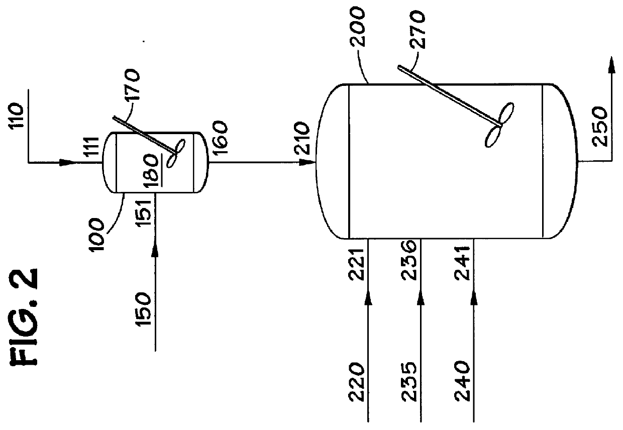
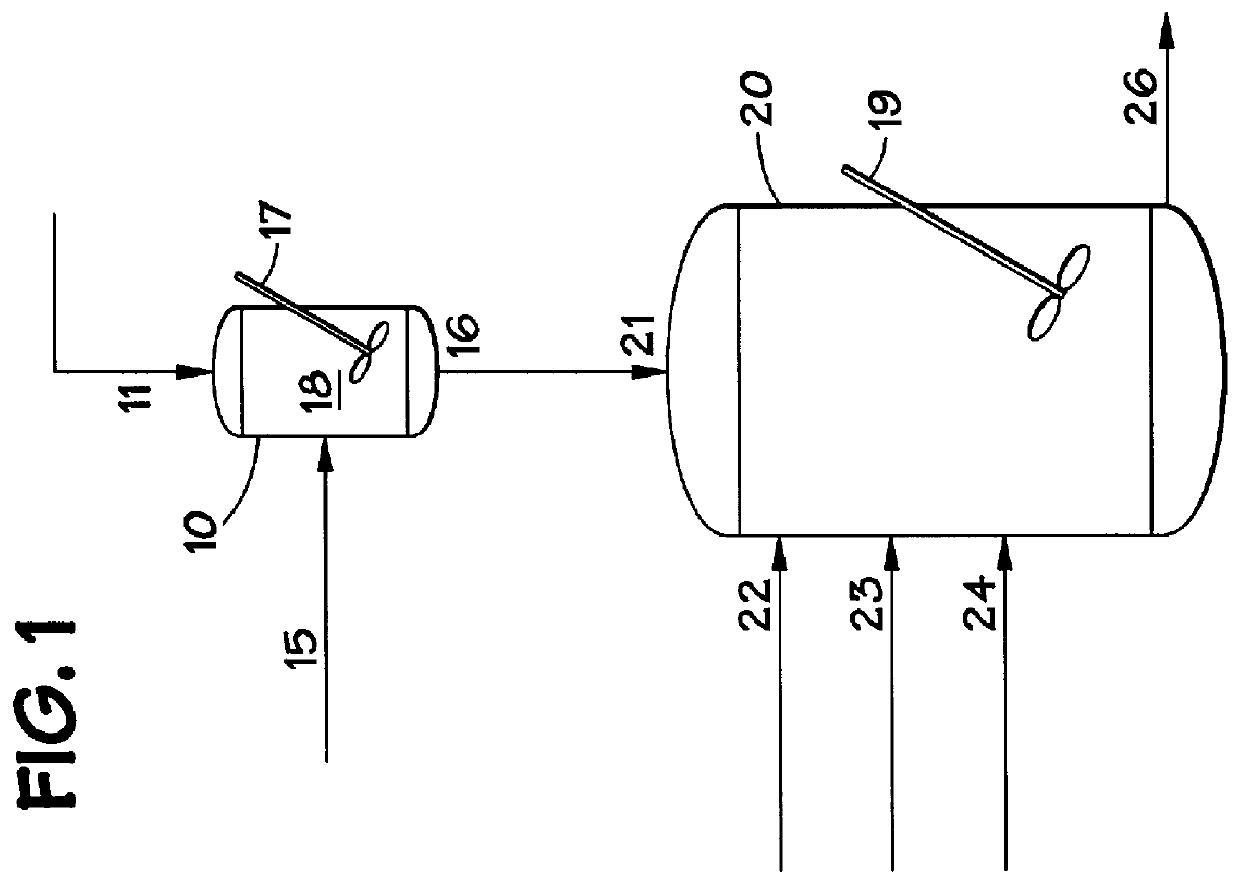
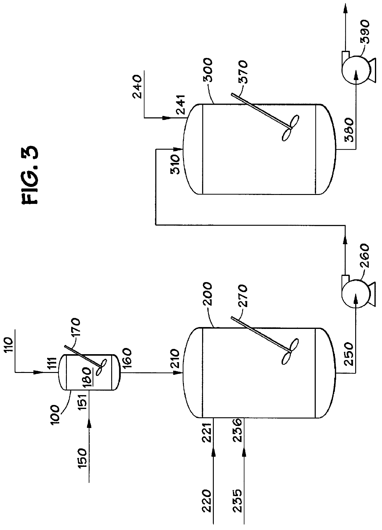
Generally speaking, the flow of liquid in a conduit, such as a pipeline, results in frictional energy losses.
While various polymerization methods and reactants have been published in the patent literature, most of those methods...

Method used


Image

  • Methods for forming amorphous ultra-high molecular weight polyalphaolefin drag reducing agents
  • Methods for forming amorphous ultra-high molecular weight polyalphaolefin drag reducing agents
  • Methods for forming amorphous ultra-high molecular weight polyalphaolefin drag reducing agents

Examples


example 1

Four different drag reducing agents were compared for their ability to increase flow of various hydrocarbons. For control purposes, all four drag reducing agents were formed from the same titanium trichloride [(TiCl.sub.3).sub.3 --AlCl.sub.3 --AKZO AA] as the transition metal catalyst. Each, however, was formed using a different co-catalyst mixture. Compositions "A" and "B" were polyalphaolefins made in accordance with the invention. Both were made using alkylaluminoxane as a co-catalyst. The co-catalyst mixture used to make composition "A" was isobutylaluminoxane (IBAO) and dibutylaluminum chloride (DIBAC); while the co-catalyst mixture used to make sample "B" was IBAO and diethylaluminum chloride (DEAC). In contrast, compositions "C" and "D" are commercially available drag reducing compositions, and were already prepared. Compositions "C" and "D" were made without use of an alkylaluminoxane.

Composition "A" was formed using 212 weight ppm based upon the weight of all the reactants ...

example

Additional tests were conducted, again, to compare the drag reducing properties of the invention, made using alkylaluminoxane co-catalysts, with the drag reducing properties of commercial DRA compositions, made without alkylaluminoxane co-catalysts. These tests were conducted over a range of concentrations. As discussed below, the results were impressive.

Again, for control purposes, all four drag reducing agents were formed using the same transition metal catalyst, i.e., titanium trichloride [(TiCl.sub.3).sub.3 --AlCl.sub.3 --AKZO Type D], but different co-catalyst mixtures. The co-catalyst mixture for composition "E" was isobutylaluminoxane (IBAO) and dibutylaluminum chloride (DIBAC). The co-catalyst mixture for composition "F" was IBAO and diethylaluminum chloride (DEAC).

Composition "E" was formed using 212 weight ppm based upon the weight of all the reactants in the reactant mixture of the same titanium trichloride [(TiCl.sub.3).sub.3 --AlCl.sub.3 --AKZO --AA]. The titanium trich...

example 3

In another specific embodiment of the invention, a drag reducing agent made using ethylene dichloride as a co-catalyst was prepared. This drag reducing agent, Composition "I", was formed using ethylene dichloride and isobutylaluminoxane as the co-catalysts.

Composition "I" was formed using 260 weight ppm based upon the weight of all the reactants in the reactant mixture of the same titanium trichloride [(TiCl.sub.3).sub.3 --AlCl.sub.3 --AKZO--AA] as used in Examples 1 and 2. The titanium trichloride was combined with 2,815 weight ppm isobutylaluminoxane (IBAO) and 96 weight ppm ethylene dichloride as co-catalysts to form a catalyst system. The catalyst system was combined with C.sub.8 (59,230 weight ppm) and C.sub.14 (59,230 weight ppm) alpha olefin monomers and a solvent (KOCH Sure-Sol-150, 868,368 weight ppm) at a temperature of -5.degree. C .in accordance with the invention and allowed to polymerize to form ultra-high molecular weight polyalphaolefins.

Composition "I" was compared ...


PUM

PropertyMeasurementUnit
Fractionaaaaaaaaaa
Timeaaaaaaaaaa
Percent by massaaaaaaaaaa

Abstract

A composition including polyalphaolefins that function as drag reducing agents and a process for the preparation of polyalphaolefins that function as drag reducing agents are disclosed. The process includes contacting alpha olefin monomers with a catalyst system, which includes a catalyst and an activator (co-catalyst) in a reactant mixture. The catalyst is a transition metal catalyst, preferably titanium trichloride, and the co-catalyst may include an alkylaluminoxane, alone or in combination, with a dialkylaluminum halide or a halohydrocarbon. The polymerization of the alpha olefin monomers produces a non-crystalline, ultra-high molecular weight polyalphaolefin having an inherent viscosity of at least 10 dL/g. The addition of the alkylaluminoxane during the polymerization process provides for a non-crystalline, ultra-high molecular weight polyalphaolefin and a more uniform molecular weight distribution of the resulting polyalphaolefin, thereby creating a drag reducing agent superior to known drag reducing agents. A process for forming a drag reducing agent comprising a non-crystalline, ultra-high molecular weight polyalphaolefin having an inherent viscosity of about at least 10 dL/g and a process for reducing drag in a conduit are also disclosed.

Description

1. Field Of The InventionThis invention relates to methods for improving flow of hydrocarbons through conduits, particularly pipelines. The invention also relates to methods for making improved drag reducing agents, and preferably, to methods for making ultra-high molecular weight amorphous polymers and copolymers of alpha olefins with improved drag reducing properties, having inherent viscosities in excess of about 10 dL / g.2. Description Of Related ArtGenerally speaking, the flow of liquid in a conduit, such as a pipeline, results in frictional energy losses. As a result of this energy loss, the pressure of the liquid in the conduit decreases along the conduit in the direction of the flow. For a conduit of fixed diameter, this pressure drop increases with increasing flow rate. When the flow in the conduit is turbulent (Reynold's number greater than about 2100), certain high molecular weight polymers can be added to the liquid flowing through the conduit to reduce the frictional ene...

Claims


Application Information

Patent Timeline
IPC IPC(8): C08F10/00C09K3/00C10L1/16C10M143/00C10M143/08C10L1/10F17D1/16F17D1/00C08F110/00C08F210/00C08F2/00C08F2/08C08F210/14C08F2/42C08F2/44C08F4/44C08F4/642C08F4/649C08F210/16C08L23/00C10M107/10
CPCC08F10/00C09K3/00C10L1/1641C10L1/165C10L1/1658C10M107/10C10M143/08F17D1/16C08F2/42C08F4/6493C08F2/002C08F4/6428C08F2/08C08F2/005C08F110/00C08F210/00C08F2500/12
Inventor EATON, GERALD B.MONAHAN, MICHAEL J.TIPTON, ROBERT J.
Owner MPOWER SPECIALTY CHEM
Why Eureka
Try Eureka