High-frequency inverter and induction cooking device using the same

a high-frequency inverter and induction cooking technology, applied in the field of high-frequency inverters, can solve problems such as noise generation of pan interferen

Inactive Publication Date: 2000-01-25
PANASONIC CORP
View PDF9 Cites 36 Cited by
  • Summary
  • Abstract
  • Description
  • Claims
  • Application Information

AI Technical Summary

Benefits of technology

Another induction heating cooker according to the present invention makes a dead time from the end point of the conducting period of the first switching element to the start point of the conducting period of the second switching element differ from a dead time from the end point of the conducting period of the second switching element to the start point of the conducting period of the first switching element. With this arrangement, a switching operation with a timing appropriate for each switching element can be executed by an easy method, thereby allowing an optimum inverter operation to be achieved.
Another induction heating cooker according to the present invention changes the capacitance of the first resonance capacitor according to the load to be heated by the coil. With this arrangement, an inverter operation appropriate for the load to be inductively heated can be achieved.
Another induction heating cooker according to the present inven

Problems solved by technology

When such a high-frequency inverter is applied to a multi-burner induction heating cooker having a plurality of heating bur

Method used


Image

  • High-frequency inverter and induction cooking device using the same
  • High-frequency inverter and induction cooking device using the same
  • High-frequency inverter and induction cooking device using the same

Examples


embodiment 1

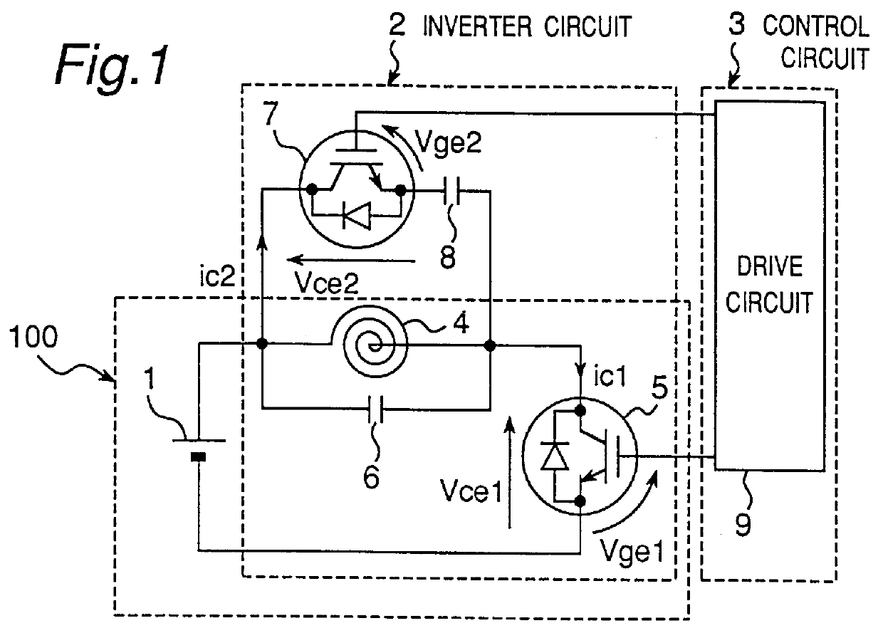
FIG. 1 shows a circuit diagram of an induction heating cooker employing a high-frequency inverter according to a first embodiment. In FIG. 1, the induction heating cooker includes: an inverter circuit 2 for converting a direct current from a DC power source 1 into a high-frequency current; and a control circuit 3 for controlling the inverter circuit 2. The inverter circuit 2 is comprised of: a one-transistor inverter 100 constructed of a heating coil 4 which serves as a heating use coil whose one terminal is connected to the positive side of the DC power source 1, an IGBT (Insulated Gate Bipolar Transistor) 5 provided with a built-in reverse conducting diode which serves as a first switching element connected between the other terminal of the heating coil 4 and the negative side of the DC power source 1 and a first resonance capacitor 6 connected in parallel with the heating coil 4; and a series circuit constructed of an IGBT 7 provided with a built-in reverse conducting diode which...

embodiment 2

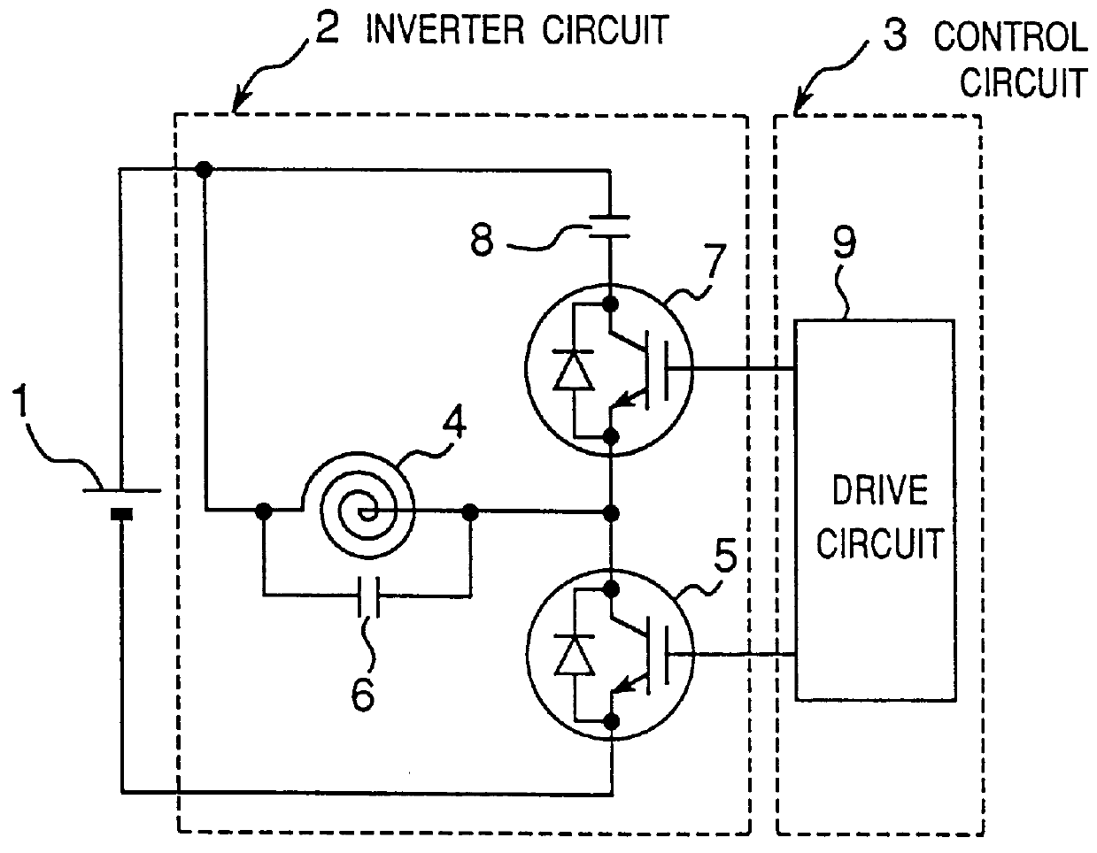
FIG. 8 shows a circuit diagram of an induction heating cooker employing a high-frequency inverter according to a second embodiment. In FIG. 8, the induction heating cooker includes: an inverter circuit 2 for converting a direct current from the DC power source 1 into a high-frequency current; and a control circuit 3 for controlling the inverter circuit 2. The inverter circuit 2 is comprised of: a heating coil 4 whose one terminal is connected to the positive side of the DC power source 1; an IGBT 5 provided with a built-in reverse conducting diode which serves as a first switching element connected between the other terminal of the heating coil 4 and the negative side of the DC power source 1; a series circuit constructed of an IGBT 7 provided with a built-in reverse conducting diode which serves as a second switching element and a second resonance capacitor 8, the series circuit connected in parallel with the heating coil 4; and a first resonance capacitor 6 connected between the c...

embodiment 3

FIG. 14 shows a circuit diagram of an induction heating cooker according to a third embodiment. In FIG. 14, the induction heating cooker includes: an inverter circuit 2 for converting a direct current from a DC power source 1 into a high-frequency current; a drive circuit 9 for controlling the inverter circuit 2; a current transformer 10 for detecting a current inputted to the inverter circuit 2; and an i.sub.in detection circuit 11 for outputting a voltage based on an output from the current transformer 10. In this case, the current transformer 10 and the i.sub.in detection circuit 11 constitute an input current detecting means for detecting the input current to the inverter circuit 2.

The inverter circuit 2 is comprised of: a heating coil 4 whose one terminal is connected to the positive side of the DC power source 1 via the primary side of the current transformer 10; an IGBT 5 provided with a built-in reverse conducting diode which serves as a first switching element connected bet...


PUM


Abstract

PCT No. PCT/JP97/00792 Sec. 371 Date Sep. 11, 1998 Sec. 102(e) Date Sep. 11, 1998 PCT Filed Mar. 13, 1997 PCT Pub. No. WO97/34446 PCT Pub. Date Sep. 18, 1997A high-frequency inverter having a simple circuit construction capable of executing a constant-frequency operation and a zero-volt switching operation and an induction heating cooker using the high-frequency inverter are disclosed. The high-frequency inverter is comprised of an inverter circuit for converting a direct current from a DC power source into a high-frequency current and a control circuit for controlling the inverter circuit. The inverter circuit is comprised of: a one-transistor inverter constructed of a heating coil whose one terminal is connected to one terminal of a DC power source, a first switching element connected in series between the other terminal of the heating coil and the other terminal of the DC power source, and a first resonance capacitor connected so as to form a resonance circuit with the heating coil; and a series circuit connected in parallel with the heating coil and constructed of a second switching element and a second resonance capacitor.

Description

The present invention relates to a high-frequency inverter which operates at a constant frequency effective for a multi-burner induction heating cooker having a plurality of burners and the like and an induction heating cooker using the high-frequency inverter.In a prior art high-frequency inverter, the operating frequency has varied according to a type of the load (pan) to be heated or a change in an input power. When such a high-frequency inverter is applied to a multi-burner induction heating cooker having a plurality of heating burners, there has been the problem that a pan interference noise is generated due to a frequency difference among the burners. As a high-frequency inverter for solving this problem, there is one disclosed in U.S. Pat. No. 5,571,438 as shown in FIG. 71. In this figure, the high-frequency inverter is comprised of a DC power source 101, an inverter circuit 102 for converting a direct current from the DC power source 101 into a high-frequency current and a c...

Claims


Application Information

Patent Timeline
IPC IPC(8): H02M7/537H05B6/06H05B6/12
CPCH02M7/537H05B6/062Y02B70/1441Y02B70/10H05B6/12
Inventor IZAKI, KIYOSHIOMORI, HIDEKIYAMASHITA, HIDEKAZUOGATA, TAIZOKITAIZUMI, TAKESHIMOKHTAR, KAMLI
Owner PANASONIC CORP
Why Eureka
Try Eureka