Apparatus and method for extracting heat from contaminated waste steam

a technology of contaminated waste steam and apparatus, which is applied in the field of apparatus and methods for extracting heat from contaminated waste steam produced, can solve the problems of large energy consumption of food processing plants, inability to readily condensate gasses, and waste of 5,000 to 7,000 pounds per hour of steam venting, so as to achieve less energy, less steam mass, and less gas to move

Inactive Publication Date: 2000-02-01
ALPHA ENGINEERS
View PDF10 Cites 67 Cited by
  • Summary
  • Abstract
  • Description
  • Claims
  • Application Information

AI Technical Summary

Benefits of technology

A means to power the flow of waste gas through the entire system is provided. This means can be located at the inlet of the waste gas surface condenser, at the inlet of the low pressure water washer, at the outlet of the low pressure water washer or beyond with secondary equipment in the waste gas flow. The means to power flow will

Problems solved by technology

Food processing plants consume vast amounts of energy, primarily in the form of steam used for steam peeling, blanching, cooking, etc., and for heating water, a substantial amount of which is used for keeping everything in the plant clean.
Assuming a raw potato feed rate of 25,000 lbs. per hour, this translates to between 5,000 to 7,000 pounds per hour of steam being wasted by venting to the atmosphere.
Since the steam is contaminated, it has always been considered pure waste.
Some of the organic gasses can be condensed at lower (cooling water) temperatures and some of these gasses cannot be readily condensed.
Fryers not having wet scrubbers waste the steam and cooking fumes to the atmosphere causing air pollution.
A heat exchanger could be used to condense the steam and heat water for other uses, but the problem with applying conventional condensing heat transfer technology to extract the heat from the waste stream is that as the steam condenses the air and other non-condensable gases co

Method used


Image

  • Apparatus and method for extracting heat from contaminated waste steam

Examples


Embodiment Construction

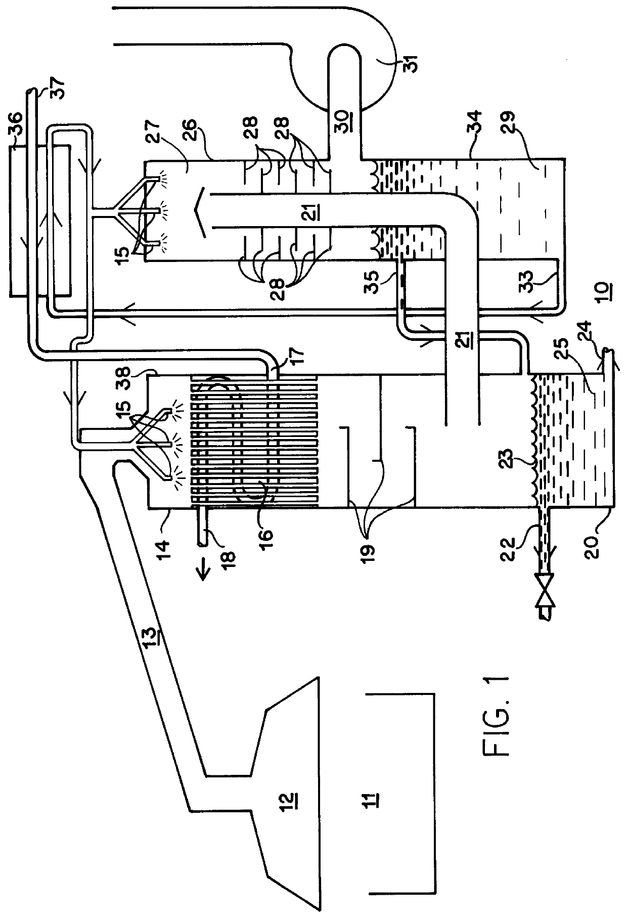
Referring now to the FIGURE, both the apparatus and the method of the invention will be described in detail. The contaminated waste steam heat recovery apparatus is generally designated as 10 and here includes a surface condensing unit 38, a low pressure water washing unit 26, a liquid-to-liquid heat exchanger 36 and a waste gas exhaust fan 31.

The surface condensing unit 38 in the preferred embodiment has an elongated and generally vertical housing which is attached at its top to the exhaust duct 13 from the exhaust hood 12 of french fry fryer 11. The surface condensing unit 38 can conceptually, and in fact is further divided or broken down into three separate subassemblies, a de-super-heating mixing chamber 14, a water-cooled condensing heat exchanger 16, and a condensate collector and reheating chamber 20. However, in this Best Mode Section, the preferred embodiment is combined surface condensing unit 38.

The waste gas is ducted from fryer 11 into a de-super-heating chamber 14 wher...


PUM

PropertyMeasurementUnit
Temperatureaaaaaaaaaa
Timeaaaaaaaaaa
Pressureaaaaaaaaaa

Abstract

Disclosed is a contaminated waste steam heat recovery apparatus 10 and method therefore which includes a primary condensing unit 38, a low pressure water washing unit 26, a liquid to liquid heat exchanger 36 and a vent fan 31. Waste gas is ducted from fryer 11 to a de-super-heating chamber 14 wherein superheated steam is converted to saturated steam by spraying water into the steam using spray nozzles 15. The gas is then introduced into a vertically disposed air to liquid heat exchanger 16 and is drafted downward therethrough. As heat is removed from the waste gas, water vapor in the steam condenses and in the process, collects some of the oil and hydrocarbons present. A plurality of condensate trays 19 are disposed below the bottom end of heat exchanger 16 in a cascading fashion to collect hold the condensate in the airflow path such that it will absorb some of the heat still present in the remaining waste gas. An oil outlet 22 is provided at the top of collection basin 22 for drawing off concentrated oil 23. The waste gas is pulled into a low pressure water washer 26 where it is washed by a second set of spray nozzles 15. Waste gas and water are sucked downward through a set of turbulence inducing baffles 28. The remaining waste gas is sucked out though exhaust tube 30, using vent fan 31, and vented to the atmosphere.

Description

1. Technical FieldThis invention generally relates to heat exchangers for extracting the heat from processing exhausts, and more particularly, this invention relates to an apparatus and method for extracting heat from the contaminated steam produced by food processing, especially french fry fryers and the like, and for reducing pollution in both the exhaust vented to the atmosphere and in the liquid effluent produced.2. Background ArtFood processing plants consume vast amounts of energy, primarily in the form of steam used for steam peeling, blanching, cooking, etc., and for heating water, a substantial amount of which is used for keeping everything in the plant clean. Upwards of 20% of the energy used in a french fry processing plant is used to heat potable water for cleaning and washing.Industrial french fry fryers are large, long, continuous feed fryers which can fry upwards of 25,000 pounds per hour of potatoes during the processing operation. The oil in which the potatoes are f...

Claims


Application Information

Patent Timeline
IPC IPC(8): B01D45/00B01D45/08B01D5/00B01D47/06B01D50/00
CPCB01D5/0081B01D5/009B01D45/08B01D47/06B01D50/004Y10S55/36B01D2221/02B01D2247/04B01D2247/105B01D2247/14Y02P70/10B01D50/40
Inventor WILLIAMS, EDDY A.
Owner ALPHA ENGINEERS
Why Eureka
Try Eureka