Controller and method for pulse welding

a pulse welding and controller technology, applied in the field of pulse welding controller and controller, can solve the problems of extreme weld puddle agitation, poor appearance of weld bead, and poor welding operation, and achieve the effects of improving pulse welding operation, great flexibility, and improving welding efficiency

Inactive Publication Date: 2000-02-15
LINCOLN GLOBAL INC
View PDF5 Cites 53 Cited by
  • Summary
  • Abstract
  • Description
  • Claims
  • Application Information

AI Technical Summary

Benefits of technology

The present invention relates to a controller, method and system for pulse welding by an electric arc welder, which controller, method and / or system control the pulse parameters in a manner to develop an improved pulse welding operation. The essence of the invention involves detecting when the molten metal ball or droplet has actually separated from the end of the consumable electrode by sensing this physical event and creating a detect signal upon the occurrence of this event. The welding process can be controlled by the detect signal to create great flexibility. In operation, the physics of the welding arc are utilized in determining droplet transfer. As the consumable electrode, with its molten metal tip, or droplet approaches the weld puddle, the arc voltage is reduced to create a negative value for the real time dv / dt. When the droplet detaches from the end of the electrode, the arc voltage increases to create a positive value for the dv / dt of the arc voltage. By calculating the rate of change of the arc voltage and detecting when the voltage, during a current pulse, shifts from a negative dv / dt to a positive dv / dt, droplet detachment is determined. Such droplet detachment occurs when there is a change in sign of the derivative of voltage from a negative value to a positive value. This event creates a detect signal which detect signal is used interactively to control the current pulse. By detecting droplet transfer, the detect signal immediately terminates the current pulse. Consequently, the energy in the pulse is set by the actual physical characteristics of the droplet transfer. This is an improvement and novel concept, which novel concept is used in a controller, method and / or system for adjusting the pulse welding process interactively. Thus, the current pulse is automatically adjusted to the desired length and energy necessary to separate the droplet from the end of the electrode during each current pulse. By merely detecting transfer of the droplet as it is propelled through the arc, the shape of the pulse, the length of the pulse, the voltage of the pulse, or other parameter can be adjusted to facilitate improved electric arc welding in the pulse mode. Essentially, the derivative of the voltage that creates the electric pulse is determined in an absolute sense and a detect signal is created when the absolute derivative changes signs from a negative value to a positive value during the actual current pulse.
Another object of the present invention is the provision of a controller, method and system as defined above, which controller, method and system control a pulse welding process or pulse welder in a manner to improve the bead and welding characteristics of the process and welder performing the process.
Yet another object of the present invention is the provision of a controller, method and system, as defined above, which controller, method and system control a parameter of the current pulse based upon a real time event during the pulse to reduce the amount of puddle agitation, spatter and / or inadvertent shorting of the electrode against the workpiece.
Still a further object of the present invention is the provision of a controller, method and system, as defined above, which controller, method and system can be used with existing electric arc welders when they are operated in the pulse mode of operation without substantial cost in the modification of the controller and without substantial changes in the overall construction of the welder or its power supply.
Another object of the present invention is the provision of a controller, method and system, which controller, method and system reduces the heat in the weld puddle and is extremely beneficial for welding thin gauge workpieces.

Problems solved by technology

However, current flowing through the arc during the welding process exerts a magnetic force on the molten puddle, pushing the puddle downwardly away from the end of the consumable electrode.
Such downward force on the molten metal in the puddle pushes the molten metal outwardly and results in a puddle depression below the electrode.
This depression and the associated electromagnetic forces can cause extreme weld puddle agitation, especially when welding metals having low specific gravity, such as aluminum.
The high energy created puddle agitation produces a poor appearance for the weld bead and unduly deep penetration of the metal into the workpiece being welded.
The amount of energy in the current pulse is important; however, it is generally compromised to optimize diverse requirements of the welding process.
If the current pulse does not contain sufficient energy, the electrode does not melt and separate before the moving electrode engages the weld puddle to create an inadvertent undesirable short circuit.
When this occurs, a substantial amount of spatter is generated in the welding process.
However, if the energy in the current pulse is too great, severe puddle agitation occurs as previously described and the molten metal on the end of the workpiece may be remelted to produce enlarged molten metal balls.
This phenomena usually causes a premature shorting during the current pulse in a subsequent weld cycle.

Method used


Image

  • Controller and method for pulse welding
  • Controller and method for pulse welding
  • Controller and method for pulse welding

Examples


Embodiment Construction

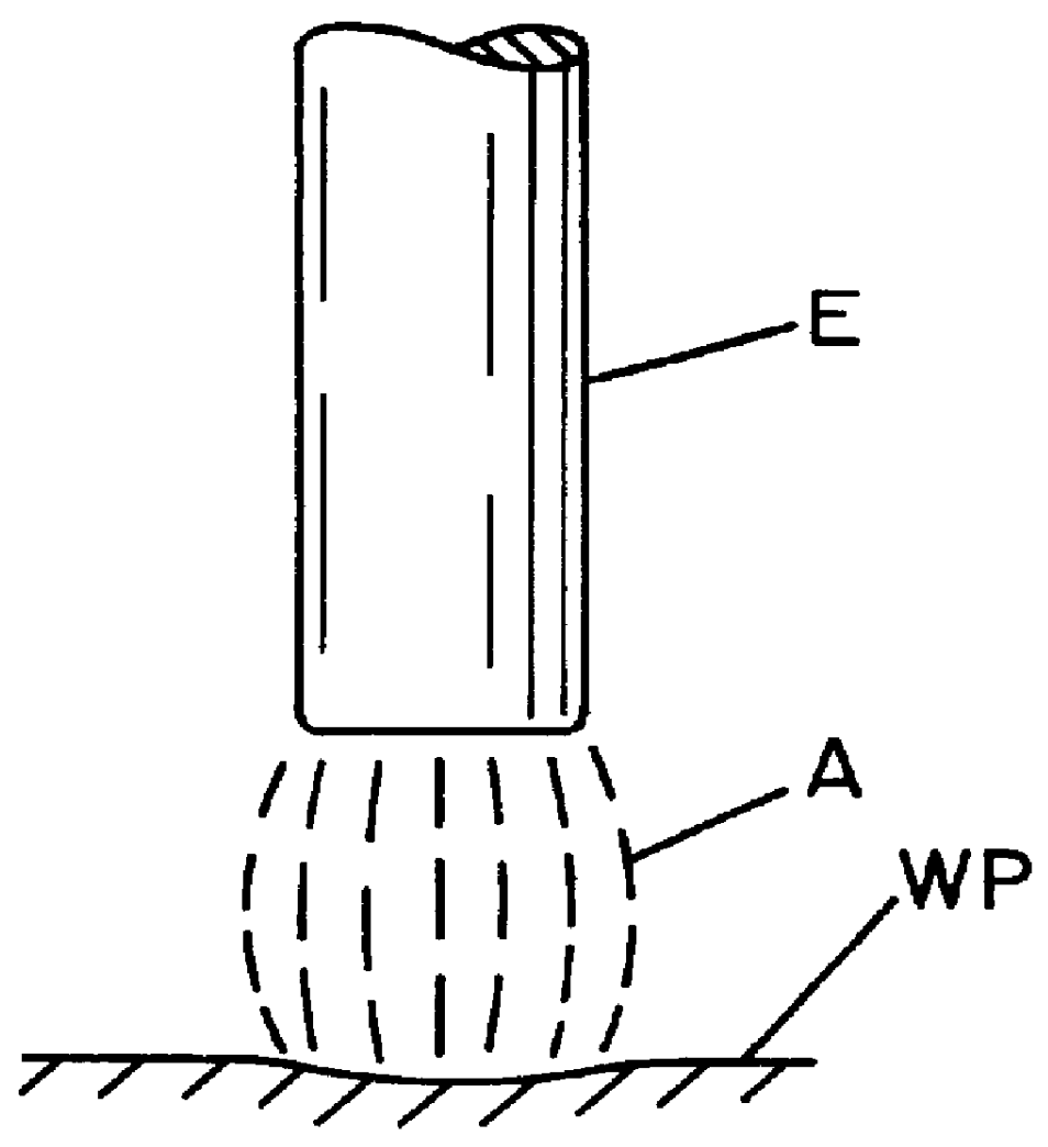
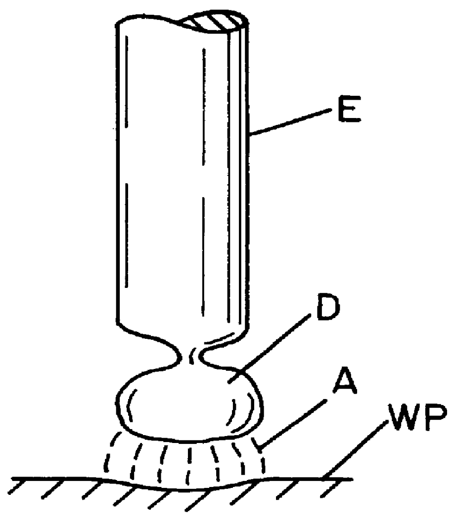
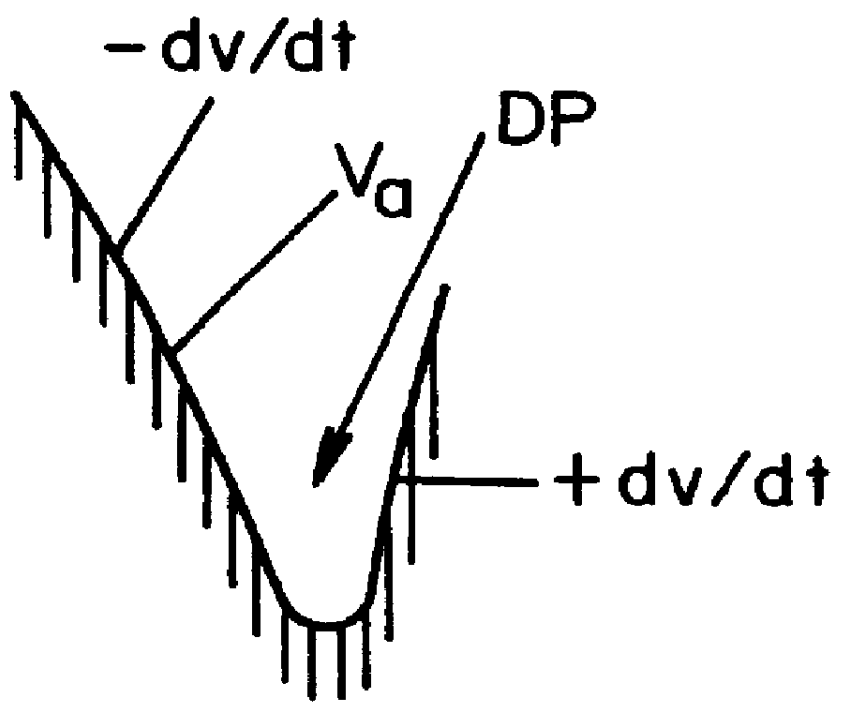
Referring now to the drawings wherein the showings are for the purpose of illustrating preferred embodiments of the present invention and not for the purpose of limiting same, FIGS. 1, 1A and 2 show the mechanics of a standard pulse welding operation wherein consumable electrode E, in the form of an advancing welding wire, is directed toward a workpiece WP in the form of a molten metal puddle. Arc A created between the electrode and workpiece melts the end of electrode E to form a molten metal mass or droplet D, which droplet is electrically pinched from the electrode by the current flow and is propelled from the electrode to the molten metal puddle by the electromagnetic force of arc A. The mechanical aspects of electric arc A during a pulse welding process, and its effect upon electrode E and workpiece WP is schematically illustrated in FIG. 2 as it relates to the current pulse C of arc current I.sub.A created by arc voltage P.sub.A.

As shown in FIG. 2, a controller for the electri...


PUM

PropertyMeasurementUnit
frequencyaaaaaaaaaa
currentaaaaaaaaaa
lengthaaaaaaaaaa

Abstract

In a power supply for creating a voltage to cause a current pulse between a consumable electrode and a workpiece to melt the end of the electrode into a droplet and propel the droplet toward the workpiece, where the power supply has a plurality of pulse controlling parameters, the improvement comprising: means for determining the real time dv / dt of the voltage during the current pulse; means for creating a detect signal in response to the real time dv / dt shifting from a negative value to a positive value; and means for adjusting at least one of the welding parameters in response to the detect signal.

Description

The invention relates to the art of arc welding and more particularly to an improved controller and method of using the controller for implementation of a pulse arc welding process.BACKGROUND OF INVENTIONSeveral arc welding methods are employed for consumable electrodes wherein the electrode is melted by current flow through the electrode, across an arc and to a workpiece. Such welding processes are divided between transfer of the molten metal from the consumable electrode to the workpiece by a surface tension, short circuit transfer mechanism or a non-short circuit transfer mechanism. In molten metal transfer of the type not involving a short circuit component, the molten metal on the end of the electrode is transferred across the electric arc to the weld puddle by way of electromagnetic forces. In such processes, the consumable if electrode should not contact the molten metal puddle constituting the workpiece. In these non-short circuit metal transfer processes for electric arc we...

Claims


Application Information

Patent Timeline
Patent Type & Authority Patents(United States)
IPC IPC(8): B23K9/09
CPCB23K9/092
Inventor STAVA, ELLIOTT K.
Owner LINCOLN GLOBAL INC
Why Eureka
Try Eureka