Coupled noise estimation method for on-chip interconnects

a technology of interconnects and coupled noise, applied in the field of integrated circuit noise measurement and noise analysis system, can solve the problems of inefficient techniques for analyzing the massive amount of interconnect data, adversely affecting neighboring signals, and more susceptible to noise failure of dynamic logic families

Inactive Publication Date: 2000-02-22
IBM CORP
View PDF4 Cites 49 Cited by
  • Summary
  • Abstract
  • Description
  • Claims
  • Application Information

AI Technical Summary

Problems solved by technology

Therefore, dynamic logic families are more susceptible to noise failure than conventional static logic.
However, these techniques are inefficient for analyzing the massive amount of interconnect data which are present in state-of-the-art integrated circuits.
As a result of the increase in the coupling capacitance, a transient voltage or current on a wire, a node, or a net can adversely affect neighboring signals.
If a circuit or net is quiet and that circuit's neighbor is active, capacitive coupling can induce a noise pulse in the quiet circuit.
This coupling phenomena can have a detrimental effect on circuit response.
For example, a coupled noise pulse can erroneously switch the state of a transistor which is required to be in a different state.
Undesired switching of a single transistor can "lock up" an entire computer system rendering the computer system unresponsive to all input.
Presently, greater utilization of noise analysis in the design phase of integrated circuits is required due to the reduced noise margin and increased noise susceptibility.
When an integrated circuit is in the design phase, the emphasis of noise failure analysis can be more urgent than the problem of timing failure analysis.
However, noise is caused by many uncontrollable variables such as capacitive coupling and input slope.
These variables are much more difficult to control after an integrated circuit is in production.
If a noise problem goes undetected to the fabrication stage, correcting the noise problem will require an expensive second fabrication run.
Circuit simulation methods are no longer sufficient to analyze noise, particularly in dynamic logic families.
Transient analysis in dynamic logic families through numerical integration or moment matching methods require considerable computational complexity and unacceptably long computation time.
Generally, model order reduction yields a complete transient response of noise waveforms, but the computational cost of model order reduction is overburdening.
Model reduction reduces the computational cost compared to complete numerical integration, but given the enormous complexity of today's interconnects, the required computation time is still unacceptable to most integrated circuit designers.
Utilizing modern moment matching methods can require more than a day to determine noise levels in a modern microprocessor circuit.
The inefficiencies are even greater if noise analysis is to be utilized within layout design systems which calculate placement and routing.
However, these simple formulas are not based upon theoretical electrical principles and hence, do not provide the required accuracy.
Currently noise analysis and noise avoidance techniques are either inaccurate or inefficient, especially for dynamic logic families.
Accurate moment matching methods or circuit simulation techniques are inefficient for both noise verification and noise avoidance.

Method used


Image

  • Coupled noise estimation method for on-chip interconnects
  • Coupled noise estimation method for on-chip interconnects
  • Coupled noise estimation method for on-chip interconnects

Examples


Embodiment Construction

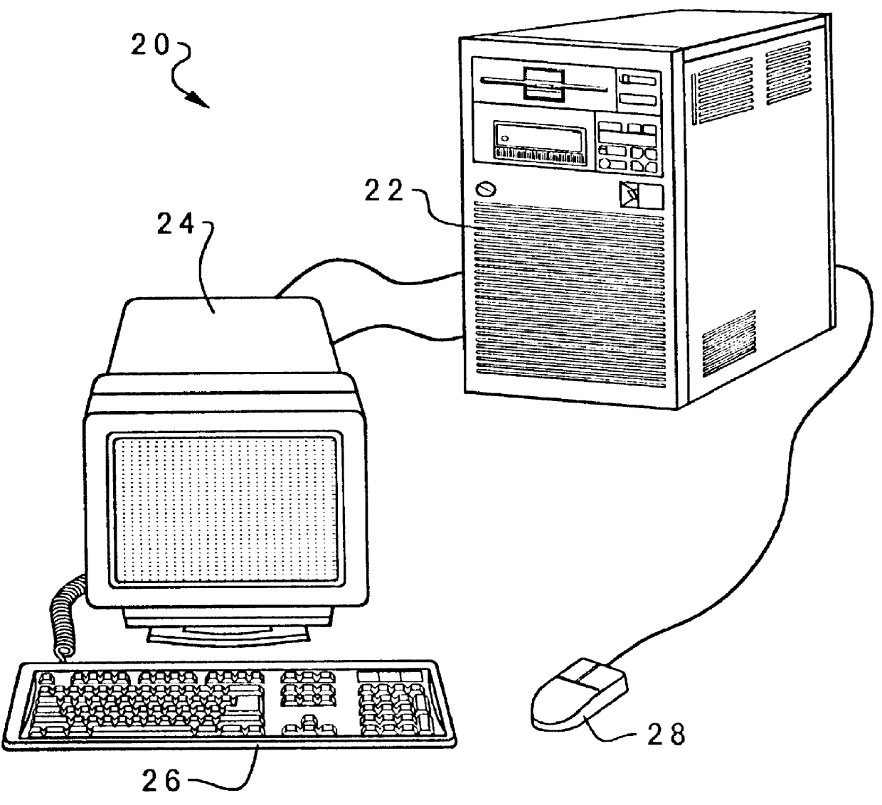
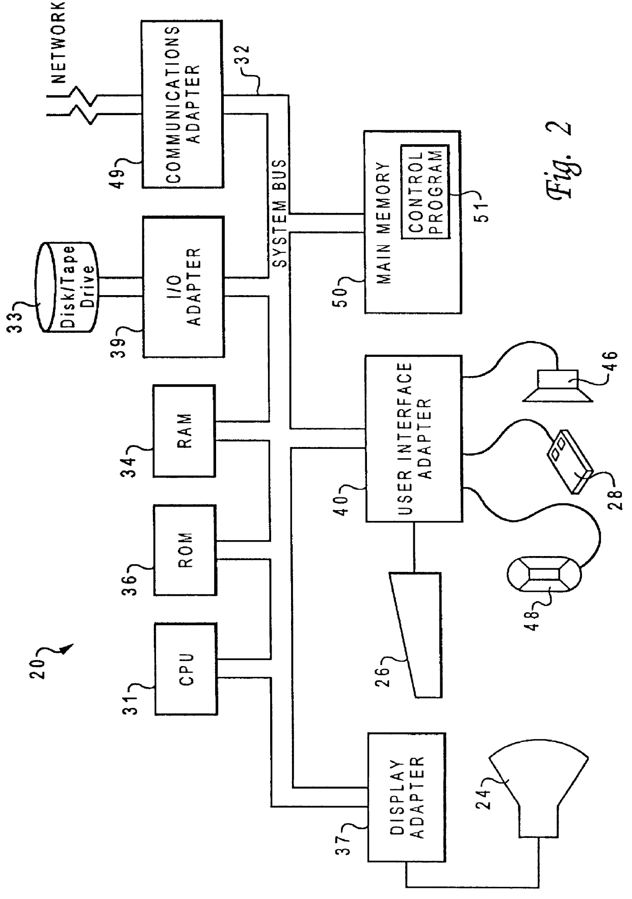
With reference now to the figures and in particular with reference to FIG. 1, there is depicted a pictorial representation of a computer system which may be utilized to implement a preferred embodiment of the present invention. A computer system 20 is depicted that includes a system unit 22, a display device 24, a keyboard 26, and a mouse 28.

System unit 22 can be implemented utilizing any suitable hardware. In a preferred embodiment, the present invention is implemented on a computer which utilizes the AIX operating system. A computer such as the IBM-RS6000 / 390, a product of International Business Machines Corporation, located in Armonk, N.Y., is well suited for implementation of the present invention. However, those skilled in the art will appreciate that a preferred embodiment of the present invention can apply to any computer system, regardless of whether computer system 20 is a conventional personal computer system or a AIX based multi-user computing apparatus.

In FIG. 1 and FIG....


PUM


Abstract

An efficient method for identifying potential noise failures in an integrated circuit design by predicting peak noise within a victim circuit of an integrated circuit. Initially, a victim circuit within an integrated circuit is located. An aggressor circuit within the integrated circuit is located which has a physical relationship with the victim circuit, normally proximity. The slope of a signal within the aggressor circuit is analyzed and the coupling currents induced in the victim circuit by the aggressor circuit are computed. The input slope of the aggressor circuit and the physical relationship between the victim circuit and the aggressor circuit are utilized to determine a peak current induced into the victim circuit utilizing modelled coupling capacitance. The peak current and the equivalent impedance of the victim circuit can be utilized to determine peak noise. Noise failures on integrated circuits can be avoided by detecting peak noise which is above acceptable levels.

Description

1. Technical FieldThe present invention relates in general to a system and method for efficiently and accurately measuring the noise susceptibility of an integrated circuit design, and in particular to a system and method which can analyze multiple circuit topologies for potential noise failure problems. Still more particularly, the present invention relates to an integrated circuit noise measuring and noise analysis system for determining the maximum noise which might be induced into a susceptible circuit.2. Description of the Related ArtAvoiding problems created by noise through noise analysis is a critical step in sub-micron integrated circuit design. Ever increasing requirements for integrated circuit performance have led to widespread utilization of dynamic logic circuit families and derivatives of dynamic logic families in integrated circuits. Dynamic logic families are aggressive circuit families, which trade noise margin for timing performance. Therefore, dynamic logic famil...

Claims


Application Information

Patent Timeline
Patent Type & Authority Patents(United States)
IPC IPC(8): G01R31/00G06F17/50
CPCG01R31/002G06F17/5036G06F30/367
Inventor DEVGAN, ANIRUDH
Owner IBM CORP
Why Eureka
Try Eureka