Process for the desulfurization of sulfur dioxide-containing gases

Inactive Publication Date: 2000-02-29
INCO +1
View PDF12 Cites 17 Cited by
  • Summary
  • Abstract
  • Description
  • Claims
  • Application Information

AI Technical Summary

Benefits of technology

The process of invention provides simplified conversion of sulfur dioxide gas into hydrogen sulfide gas. First, sulfur dioxide gas is absorbed into an aqueous sulfide solution to form mainly sulfite and bisulfide ions. Second, additional sulfur dioxide gas is absorbed into the aqueous solution to form hydrogen sulfide. Third, another portion of the sulfur dioxide is absorbed and reacts to form bisulfite. Most advantageously, the bisulfite is decomposed into sulfur dioxide and sulfite. The sulfite is then reduced to sulfide and returned for use in the absorption process. The hydrogen sulfide may then be reacted with SO.sub.2 via the Claus reaction to form elemental sulfur.

Problems solved by technology

Second, additional sulfur dioxide gas is absorbed into the aqueous solution to form hydrogen sulfide.

Method used


Image

  • Process for the desulfurization of sulfur dioxide-containing gases
  • Process for the desulfurization of sulfur dioxide-containing gases
  • Process for the desulfurization of sulfur dioxide-containing gases

Examples


example 1

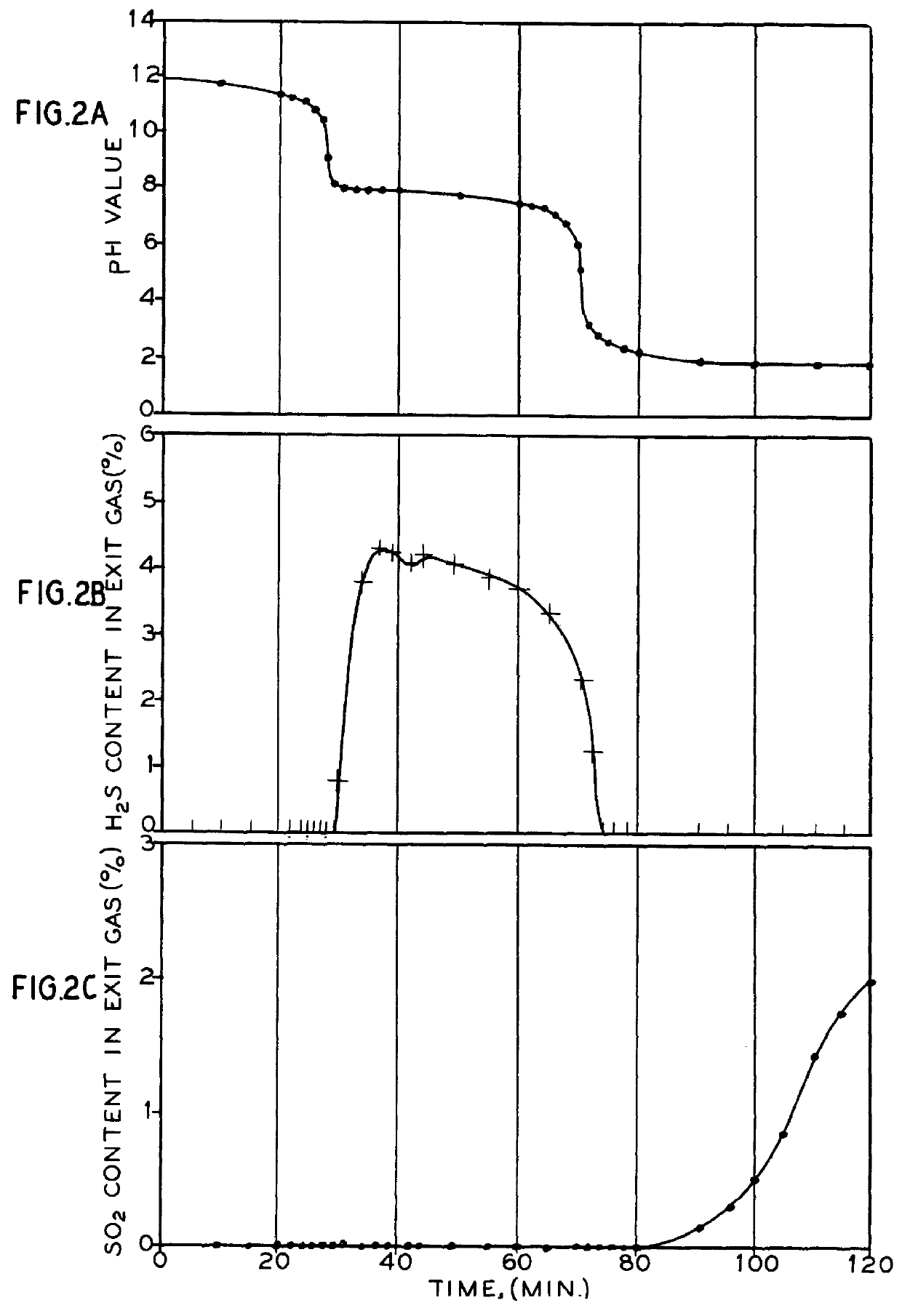
In a semi-flow batch reactor, the reaction gas is fed into the system at a constant rate of 100 ml / min under standard temperature and pressure conditions without adding fresh solution during the reaction. The reactor contained 400 ml of 0.1 M Na.sub.2 S solution constantly stirred and maintained at a temperature of 35.degree. C. A feed gas having a composition of 9.29% SO.sub.2, 2.14% O.sub.2 and balance nitrogen with incidental impurities was introduced into the reactor through a bubble distributor.

As shown in FIGS. 2a, 2b and 2c, a three-stage pattern was observed, when the experiment was conducted in the semi-flow batch reactor. In the first stage, all sulfur dioxide in the feed gas is removed by the solution without the release of significant quantities of hydrogen sulfide. The first stage ends with the beginning of hydrogen sulfide generation. In the second stage, hydrogen sulfide forms with complete removal of sulfur dioxide from the feed gas. The second stage ends when no mor...

example 2

When a continuous flow tank reactor was used, higher conversion ratios of hydrogen sulfide to sodium sulfide were observed. The conversion of sodium sulfide to hydrogen sulfide could be over 90%, when 10% SO.sub.2 gaseous mixture and 1.44 M sodium sulfide solution were used at 90.degree. C. The flow rate of the feed gas was 540 ml / min through a bubble distributor, as measured under standard temperature and pressure conditions. The flow rate of the feed liquid was 1.0 ml / min. The reactor was continuously stirred. The continuous flow tank reactor produced an exit gas stream having an H.sub.2 S concentration of 6.2%. No sulfur dioxide was detected in the exit gas stream. The molar ratio of the H.sub.2 S generated to Na.sub.2 S supplied into the reactor was greater than 0.9. The molar ratio of the SO.sub.2 absorbed in the reactor to the Na.sub.2 S supplied to the reactor was about 1.6. The pH of the reactor solution was measured to be 8.4.

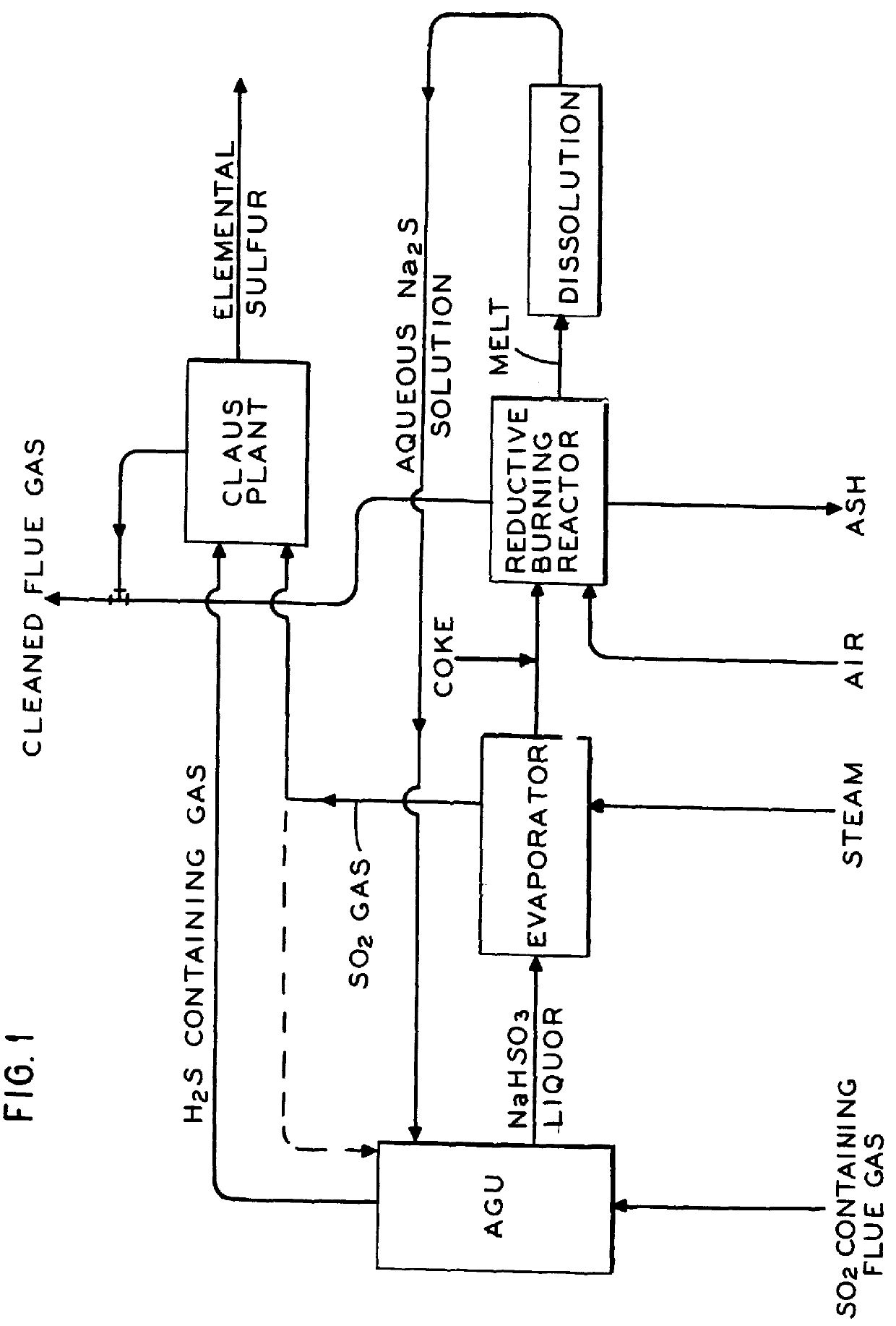
A summary of the overall process of the inventio...


PUM

PropertyMeasurementUnit
temperatureaaaaaaaaaa
oxidation-reduction potentialaaaaaaaaaa

Abstract

The process of invention provides a simplified conversion of sulfur dioxide gas into hydrogen sulfide gas. First, sulfur dioxide gas is absorbed into an aqueous sulfide solution to form sulfite and bisulfide ions. Second, additional sulfur dioxide gas is absorbed into the aqueous solution to form hydrogen sulfide. Third, another portion of the sulfur dioxide is absorbed and reacts in the aqueous solution to form bisulfite. Most advantageously, the bisulfite is decomposed into sulfur dioxide and sulfite. The sulfite is then reduced to sulfide and returned for use in the absorption process. The hydrogen sulfide may then be reacted with SO2 via the Claus reaction to form elemental sulfur.

Description

This invention relates to the desulfurization of sulfur dioxide-containing gases. This invention particularly relates to the conversion of sulfur dioxide gas into hydrogen sulfide gas.BACKGROUND OF THE ART AND PROBLEMThe removal of sulfur dioxide from industrial flue gases such as that produced by non-ferrous sulfide smelters and fossil fuel-burning power plants, has become a common commercial practice. Effective removal of sulfur dioxide from flue gases, and its conversion into environmentally safe products has become an expensive operation. Reducing the cost of sulfur dioxide removal has the potential of benefiting industry, consumers and the environment.In conventional sulfur dioxide removal technologies, sulfur dioxide in flue gases may be fixed as one of the following materials, sulfuric acid, liquid sulfur dioxide, elemental sulfur or calcium sulfite / sulfate. The strength of the sulfur dioxide source usually determines the ultimate end product. The limited storage capability a...

Claims


Application Information

Patent Timeline
Patent Type & Authority Patents(United States)
IPC IPC(8): B01D53/50C01B17/04C01B17/00C01B17/05C01B17/16
CPCB01D53/507C01B17/0404C01B17/05C01B17/164
Inventor LU, WEI-KAOJIA, CHARLES QIANGHEGDE, VISHWAPRAKASH SATYANARAYANNG, STEVEN HOI-CHIU
Owner INCO
Why Eureka
Try Eureka