Electron beam proximity correction method for hierarchical design data

Inactive Publication Date: 2000-03-07
GLOBALFOUNDRIES INC
View PDF10 Cites 36 Cited by
  • Summary
  • Abstract
  • Description
  • Claims
  • Application Information

AI Technical Summary

Problems solved by technology

This scattering of electrons may result in distortions to the desired pattern.
An increase in the number of devices and elements on a chip increases the chip density and complexity.
The chip density and complexity is further increased as features become smaller in size.
Despite the significant computational advantages offered by the dose-on-grid technique, the data compaction of the original design hierarchy is lost, s

Method used


Image

  • Electron beam proximity correction method for hierarchical design data
  • Electron beam proximity correction method for hierarchical design data

Examples


Embodiment Construction

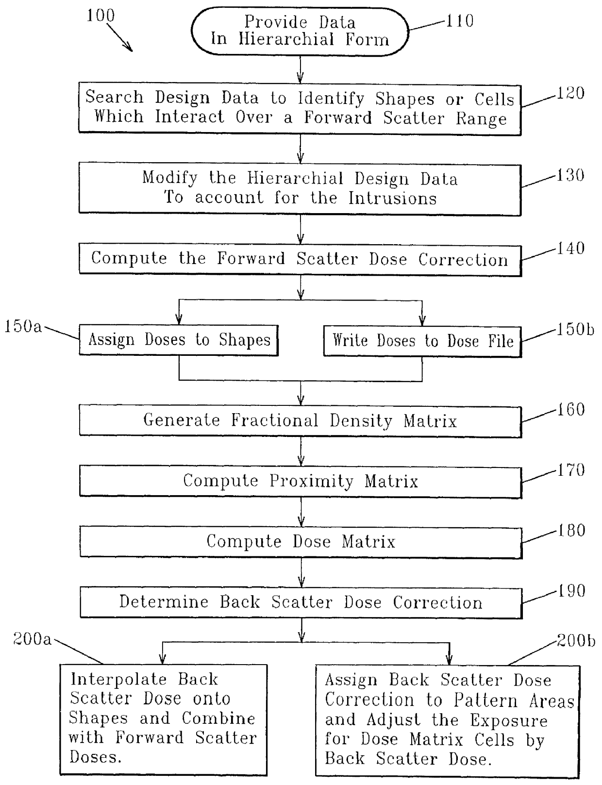
Referring now in detail to FIG. 1, in which a method of the present invention is illustrated, and generally referred to by reference numeral 100. The method formulates an exposure dose for an electron beam on a resist film for a pattern of geometric shapes compensating for electron scattering effects, in which the design data is provided in step 110 in hierarchial form. The design data consists of a library of cell types specifying the geometric shapes and their respective cells.

The hierarchy is then searched in step 120 to identify shapes from different cells which interact over the forward scatter range, a.alpha.. The interacting shapes are referred to as intrusions. The searching step 120 determines if intrusions exist in the hierarchial pattern layout.

The design hierarchy is then modified in step 130 by either moving the intruding shapes into the cells with which they interact, or by creating variant cells in which the presence of the intruding shapes is recognized. For typical ...


PUM


Abstract

A method for formulating an exposure dose for an electron beam on a resist film for a pattern of geometric shapes which compensates for electron scattering effects utilizing hierarchial design data which is preserved to as great as an extent as possible in the computation of the exposure dose. The exposure dose is corrected for both the forward scatter and backscatter effects of the electron beam in which the design data is modified for interactions of shapes which are affected only over the forward scatter range. In another version of the method, a multiple Gaussian approximation is used where the short term Gaussian terms are treated as the forward scatter terms and the long term Gaussian terms are treated as the back scatter terms.

Description

1. Field of the InventionThe present invention generally relates to the technology of electron beam lithography, and more specifically to a method for proximity effect correction in electron beam lithography systems.2. Description of the Prior ArtIn recent years, various electron beam lithography systems have been employed to write fine patterns on samples such as semiconductor wafers. The samples are typically covered by a thin film called a resist. The resist properties are modified by exposure to an electron beam according to a desired pattern. The patterned resist film is used as a stencil for subsequent processing. Electrons emitted towards the sample collide with nuclei, etc., of the sample and scatter. This is called backward scattering. A phenomenon called forward scattering also occurs. Forward scattering is the electron scattering that occurs in the resist prior to entry into the substrate. Forward scattering also represents the finite beam spread in real electron beam sys...

Claims


Application Information

Patent Timeline
IPC IPC(8): H01J37/302H01J37/30
CPCH01J37/3023H01J2237/31769
Inventor GERBER, PORTER DEANWIND, SAMUEL JONAS
Owner GLOBALFOUNDRIES INC
Why Eureka
Try Eureka