
Amorphous alloy catalyst containing boron, its preparation and use

Inactive Publication Date: 2000-03-14
CHINA PETROCHEMICAL CORP +2
View PDF2 Cites 4 Cited by
  • Summary
  • Abstract
  • Description
  • Claims
  • Application Information

AI Technical Summary

Benefits of technology

The catalyst of the present invention exhibits excellent thermal stability. Its maximum crystallization temperature is higher than 350.degree. C., which is 9.6.degree. C. higher than the ultra-fine Ni-B amorphous alloy (its highest crystallization temperature is 341.42.degree. C.). Their thermal stability could be further improved by introducing those metal additives (M) which have a larger atomic size and could form an amorphous alloy with Ni-B. For example, the highest crystallization temperature of Ni-B amorphous alloys with Zn, Mo, and W metal additives, could reach 411.degree. C., 429.degree. C., and 430.degree. C., respectively.

Problems solved by technology

One problem concerns how to increase the surface area of the amorphous alloy catalyst, so that its catalytic activity can be improved.
The other problem concerns how to keep the catalyst in its amorphous state, i.e. how to enhance the thermal stability of the amorphous alloy catalyst.
However, ultra-fine Ni-B amorphous alloy particles obtained in this manner exhibited poor thermal stability, although their surface area was determined as high as 29.7 m.sup.2 / g.
Since all of these three reactions proceed very rapidly, efficient deposition of the resulting Ni-B amorphous alloy on the support could not be guaranteed when chemical plating is carried out by mechanically mixing the support and the plating solution, nor could the homogeneous distribution of Ni-B amorphous alloy on the support be assured.
Therefore, the deposition of a Ni-B amorphous alloy on the support becomes a difficult problem in this field.
Up to now, although various attempts have been made to improve both the reactivity and thermal stability of the amorphous alloy catalysts, unfortunately, no catalysts reported thus far can match the Ni-RE-P amorphous alloy catalyst with respect to its high surface area as described in CN 1,073,726A, or with respect to their catalytic activity.

Method used


Image

  • Amorphous alloy catalyst containing boron, its preparation and use
  • Amorphous alloy catalyst containing boron, its preparation and use
  • Amorphous alloy catalyst containing boron, its preparation and use

Examples


examples 1-22

(1) Carriers

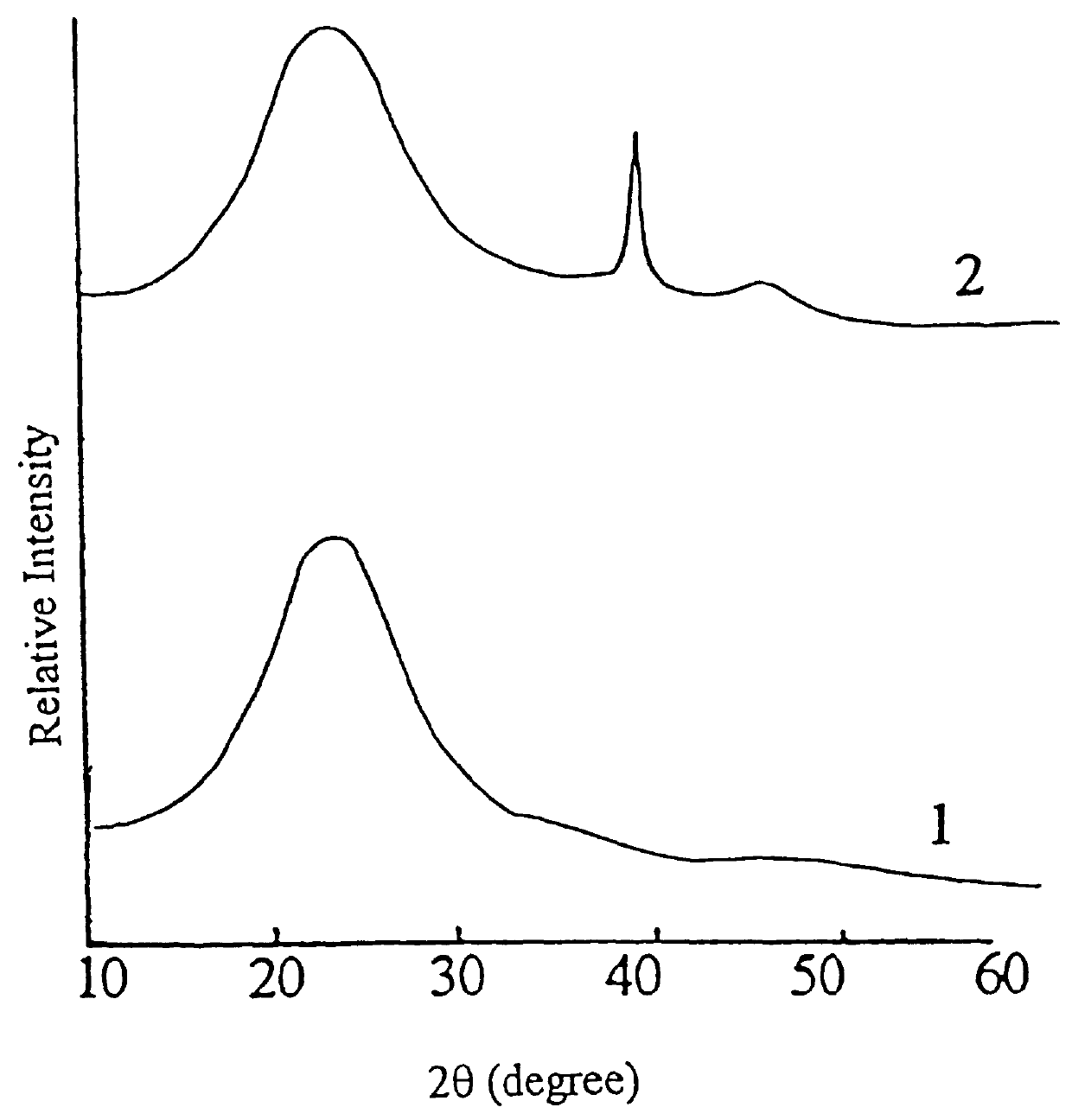
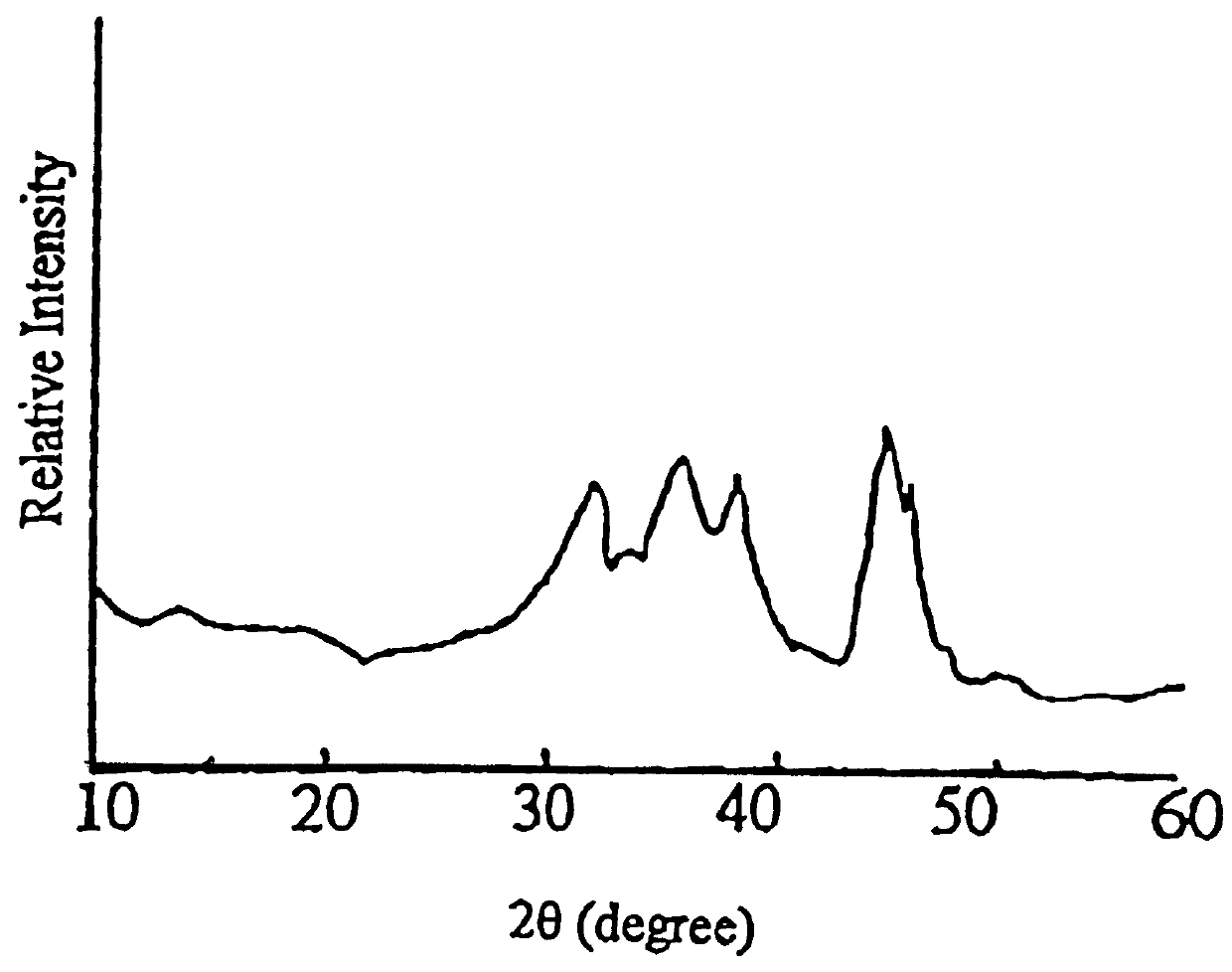
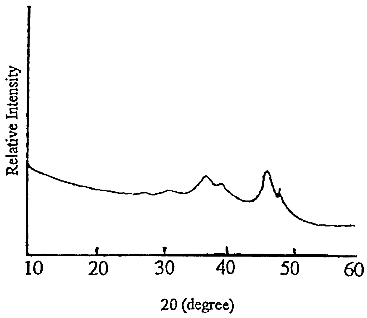
Carrier 1 (No. Z.sub.1) refers to silica gel with a large pore size which is available from Qingdao Haiyang Chemical and Engineering Company, China. Carrier 2 (No. Z.sub.2) refers to silica gel with a small pore size which is available from the same company as mentioned above. Carrier 3 (No. Z.sub.3) refers to the .delta.-Al.sub.2 O.sub.3 which is prepared by calcining spherical Al.sub.2 O.sub.3 at 900.degree. C. for 4 hours, which itself is used as the carrier for CB-8 catalyst and is available from Changling Catalyst Company, China. Carrier 4 (No. Z.sub.4) refers to .gamma.-Al.sub.2 O.sub.3 which is prepared by calcining spherical Al.sub.2 O.sub.3 at 650.degree. C. for 4 hours, which is also used as the carrier of CB-8 catalyst and is available from Changling Catalyst Company, China. The physiochemical properties of these four carriers (Z.sub.1 -Z.sub.4) are summarized in Table 1, in which the crystalline phases are determined by XRD, the surface area and pore volume a...

examples 23-24

Described below is the preparation of catalysts 23-24 according to the present invention.

(1) Carriers

Carrier 5 (No. Z.sub.5) is amorphous SiO.sub.2 available from Shanghai Silicate Institute, China. Carrier 6 (No. Z.sub.6) is .alpha.-Al.sub.2 O.sub.3. Their surface area and pore volume as well as crystalline phases are listed in Table 7.

(2) Catalyst Preparation

(a) The amounts of each of the above mentioned carriers Z.sub.5 and Z.sub.6 listed in Table 8 are dried at 120.degree. C. The amounts of NiCl.sub.2 and CoCl.sub.2 listed in Table 8 are dissolved in the appropriate amount of distilled water, also listed in Table 8, to prepare the mixed NiCl.sub.2 and CoCl.sub.2 solution, which is then used for immersing the above carriers, Z.sub.5 and Z.sub.6. After the impregnated carriers are dried at 120.degree. C., the KBH.sub.4 aqueous solution prepared from the amounts of KBH.sub.4 and water listed in Table 8, is added dropwise to the carriers. After the reaction is completed, which is in...

examples 25-32

The preparation of the catalysts C.sub.25 -C.sub.32 according to the present invention.

The amount of Z.sub.5 carrier listed in Table 10 is dried at 120.degree.. The listed weights of NiCl.sub.2 and the chlorides of the metal additives from Table 10 are dissolved in the amount of distilled water from Table 10, to prepare the mixed solution containing Ni.sup.2+ and the ions of a metal additive (M). This solution is then used for immersing the above carrier Z.sub.5. After the immersion step, the carriers are dried at 120.degree. C., and to the carriers are added dropwise a solution containing the amount of KBH.sub.4 listed in Table 10. After the reaction is completed, which is indicated when no more significant amount of H.sub.2 is released, the resulting solid products are washed with distilled water until it is free from acidic ions. The resulted catalysts according to the present invention are numbered as C.sub.25 to C.sub.32, corresponding to experiment numbers 25 to 32 from Table ...


PUM

PropertyMeasurementUnit
Lengthaaaaaaaaaa
Angleaaaaaaaaaa
Lengthaaaaaaaaaa

Abstract

The present invention discloses an amorphous alloy catalyst containing boron, which is composed of a porous carrier, a Q-B amorphous alloy, and a metal additive (M), the content of Q-B amorphous alloy together with metal additive is from 0.1 to 60 wt %, based on the total weight of the catalyst, in which the atomic ratio (Q+M) / B is 0.5-10, and the Q / M atomic ratio is 0.1-1000; wherein Q represents an metal selected from group VIII and B represents boron; and said metal additive (M) refers to those one or more metal elements which can be reduced to its / their elemental states from the corresponding salts by a solution containing BH4- with the exception that M is not the one which is used as Q. Said catalyst exhibits high catalytic hydrogenation activity.

Description

The present invention relates to an amorphous alloy catalyst and its preparation and use. In more detail, the invention relates to an amorphous alloy catalyst containing a metal (Q) selected from group VIII of the periodic table, and boron, and to its preparation and use.The following two problems need be overcome during the development of the amorphous alloy catalysts. One problem concerns how to increase the surface area of the amorphous alloy catalyst, so that its catalytic activity can be improved. The other problem concerns how to keep the catalyst in its amorphous state, i.e. how to enhance the thermal stability of the amorphous alloy catalyst. Numerous previous attempts have been directed toward addressing these problems.In CN1,073,726A, an alloy containing Al, rare earth elements (RE), P, and Ni or Co or Fe was prepared by rapid quenching techniques. By alkaline leaching Al from the alloy with NaOH, a Ni / Co / Fe-RE-P amorphous alloy catalyst with high surface area up to 50-130...

Claims


Application Information

Patent Timeline
IPC IPC(8): B01J21/02B01J21/00C07C209/48C07C209/00C07C5/11C07C29/00C07C5/09C07B31/00C07C51/36C07C51/347C07C29/145C07C5/00C07C5/10C07C51/367C07C7/167C07C7/00C07C211/00C07C211/46C07C211/11C07C211/12B01J23/54B01J23/76B01J29/064B01J37/18C07B61/00C07C5/02C07C11/04C07C13/20C07C13/23C07C15/073C07C209/36
CPCB01J21/02B01J23/755B01J23/83B01J23/85B01J23/8933C07B31/00C07C5/09C07C5/10C07C5/11C07C7/167C07C29/145C07C51/36C07C51/367C07C209/48B01J23/63C07C15/46C07C13/18C07C13/23C07C11/04C07C53/124C07C65/01C07C211/11C07C211/12C07C211/46C07C35/08C07C2523/755C07C2101/14C07C2101/16C07C2521/02C07C2601/14C07C2601/16Y02P20/52
Inventor MIN, ENZEDENG, JINGFAMA, AIZENGLU, WANZHEN
Owner CHINA PETROCHEMICAL CORP
Learn More