Extremely-thin steel sheets and method of producing the same

a technology of ultra-thin steel and production method, which is applied in the direction of furnaces, heat treatment devices, work heating devices, etc., can solve the problems of poor welding, natural inability to avoid the lowering of can strength, and severe control of the accuracy of hardness and dimensional precision and flatness of steel sheets, so as to improve the weldability, and improve the corrosion resistance and rust resistance. small

Inactive Publication Date: 2000-03-28
KAWASAKI STEEL CORP
View PDF8 Cites 20 Cited by
  • Summary
  • Abstract
  • Description
  • Claims
  • Application Information

AI Technical Summary

Benefits of technology

Moreover, the C content is favorable to be more than 0.004 but not more than 0.05 wt % for improving the workability after welding, or to be not more than 0.004 wt % for improving the deep drawability.
And also, the reason why the weight ratio of Ni / (Fe+Ni) and the thickness in Fe--Ni alloy layer are limited to 0.01-0.3 and 10-4000 .ANG. is due to the fact that when the weight ratio of Ni / (Fe+Ni) is less than 0.01, the effect of improving the corrosion resistance and rust resistance is not obtained, while when it exceeds 0.3, the Fe--Sn--Ni alloy layer after the reflow treatment becomes coarse and the covering ratio becomes small to degrade the corrosion resistance and rust resistance. And also, when the thickness is less than 10 .ANG., the effect of improving the corrosion resistance and rust resistance is small, while when it exceeds 4000 .ANG., cracks are created in the hard and brittle Fe--Ni alloy to degrade the corrosion resistance and rust resistance.

Problems solved by technology

In the steel sheet for can, therefore, it was required to severely control not only the accuracy of the hardness but also dimensional precision and flatness of the steel sheet, lateral bending of steel strip and the like as compared with steel sheets for automobile.
When the thickness is made thin, it is naturally impossible to avoid the lowering of the can strength.
Because, when the film is laminated to the weld portion at a state of slightly shifting from the given set position, poor welding is caused to bring about large damage.
Therefore, the can height became unnecessarily higher in the widthwise central portion of the plate width being apt to be thickened to thereby decrease the yield, but also when the can body was taken off from a press machine, an upper portion of the can body was engaged with the press machine to prevent the removal from the machine and a new can body was charged in the machine before the removal and hence jamming phenomenon that plural can bodies were pressed several times was caused to largely damage the productivity.
In the 3-piece can, the can body was apt to become flat even if it was wound in form of a cylinder after flexor and hence the cylindrical body having a higher true circle was not obtained and there were problems that the thickness was locally thinner and the can strength was lacking even when using an extremely-thin and wide-width steel sheet for can having a high strength.
If a hard portion and a soft portion are mixedly existent in the widthwise direction of the steel strip, even when the rolling is carried out under the same rolling directions, the elongation of the soft portion is large and the elongation of the hard portion is small and hence the flatness becomes poor.
Even if the poor flatness resulting from such a material property is apparently corrected by mechanical correction such as tension leveler or the like, when small blanks are subsequently formed by slit-cutting every can unit, local warping is again caused and hence there is caused a new problem that high-speed can formation becomes difficult.
In the conventional technique, however, it was possible to merely produce the wide-width steel strip in view of the installation, but it was difficult to rationally correspond with the requirements as previously mentioned and there were, for example, problems that the thickness was thinned from the set value and the material properties were missed and the dimensional precision was poor.
Particularly, these qualities were degraded in widthwise end portion and longitudinal end portion of the steel strip, so that there was a problem that these end portions were cut out and removed at the production step of the steel sheet to considerably lower the yield.
Even if steel strips having a width wider than the above were manufactured, it was difficult to provide substantially uniform thickness and material properties over not less than 95% of the width.
As a large factor obstructing the uniformity of the material properties, there are considered segregation of steel components and ununiformity of temperature in hot rolling and annealing.
Therefore, the remaining problem in the operation is considered to mainly lie in the hot rolling.
In the extremely-thin and wide-width steel sheet, however, a variation of plate crown of not less than about 40 .mu.m was caused, so that the above control was insufficient from a viewpoint of ensuring the uniformity of material properties.
In any case, the conventional technique had a problem that the widthwise end portion and longitudinal end portion were cut out and removed by trimming operation or the like until the finish of a product as a steel sheet for can to largely lower the yield.
However, when such a steel sheet was produced by the conventional production technique, there was a problem that the thickness and material properties (particularly hardness) were obliged to be ununiform in the widthwise direction.
Furthermore, the lowering of product yield resulted from the poor shape of the can body and poor strength was brought about even in the production of the can body using such a steel sheet and hence new can forming method based on film laminated coil, coat coil or the like could not effectively be applied.

Method used


Image

  • Extremely-thin steel sheets and method of producing the same
  • Extremely-thin steel sheets and method of producing the same
  • Extremely-thin steel sheets and method of producing the same

Examples


example 2

A cold rolled steel sheet was produced from steel having a chemical composition shown in Table 7 in the same manner as in Example 1. A surface-treated steel sheet was produced by subjecting the surface of the steel sheet to plating and, if necessary, reflow treatment and then to a chromate treatment.

The above producing conditions are shown in Table 8 and Table 9. Moreover, steel No. 2 was subjected to an averaging treatment of 500.degree. C., 30 seconds in the continuous annealing.

The surface treating conditions were as follows.

As the usual tin plating not subjected to Ni diffusion treatment, tin plating or thin tin plating was carried out in a halogen type electric tin plating step, which was continuously subjected to reflow treatment and chromate treatment to obtain tin plate.

A tin-free steel sheet (TFS) was subjected to a plating in a chromate solution containing CrO.sub.3 : 180 g / l, H.sub.2 SO.sub.4 : 0.8 g / l at a metallic chromium quantity of 30-120 mg / m.sup.2 and subsequently ...

example 3

Steel having a chemical composition shown in Table 13 was melted in a bottom-blowing converter of 270t and cast by means of a continuous casting machine to obtain a cast slab.

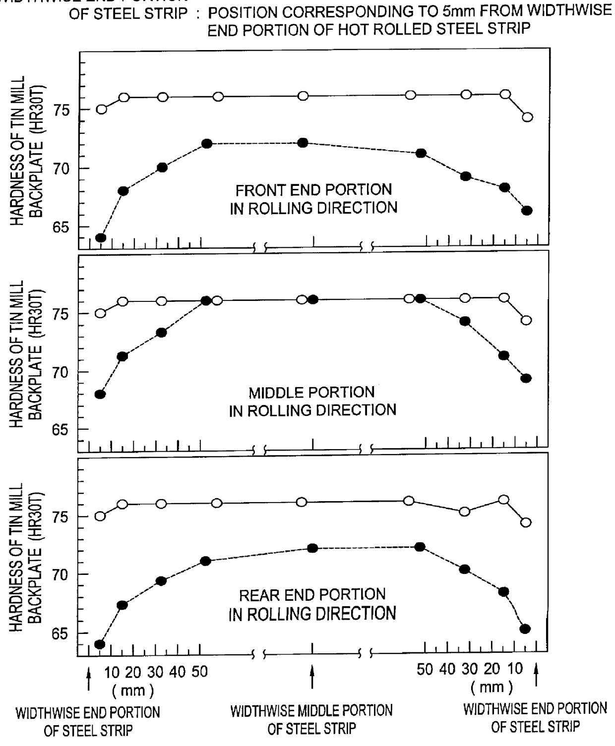
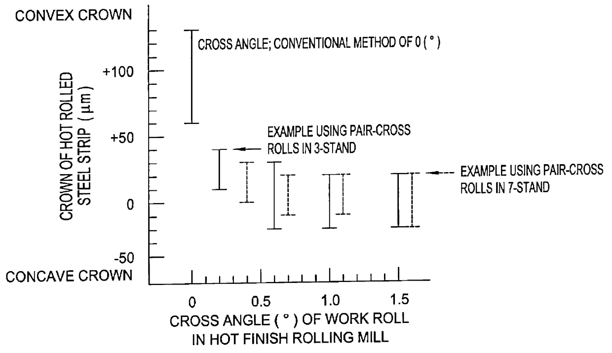
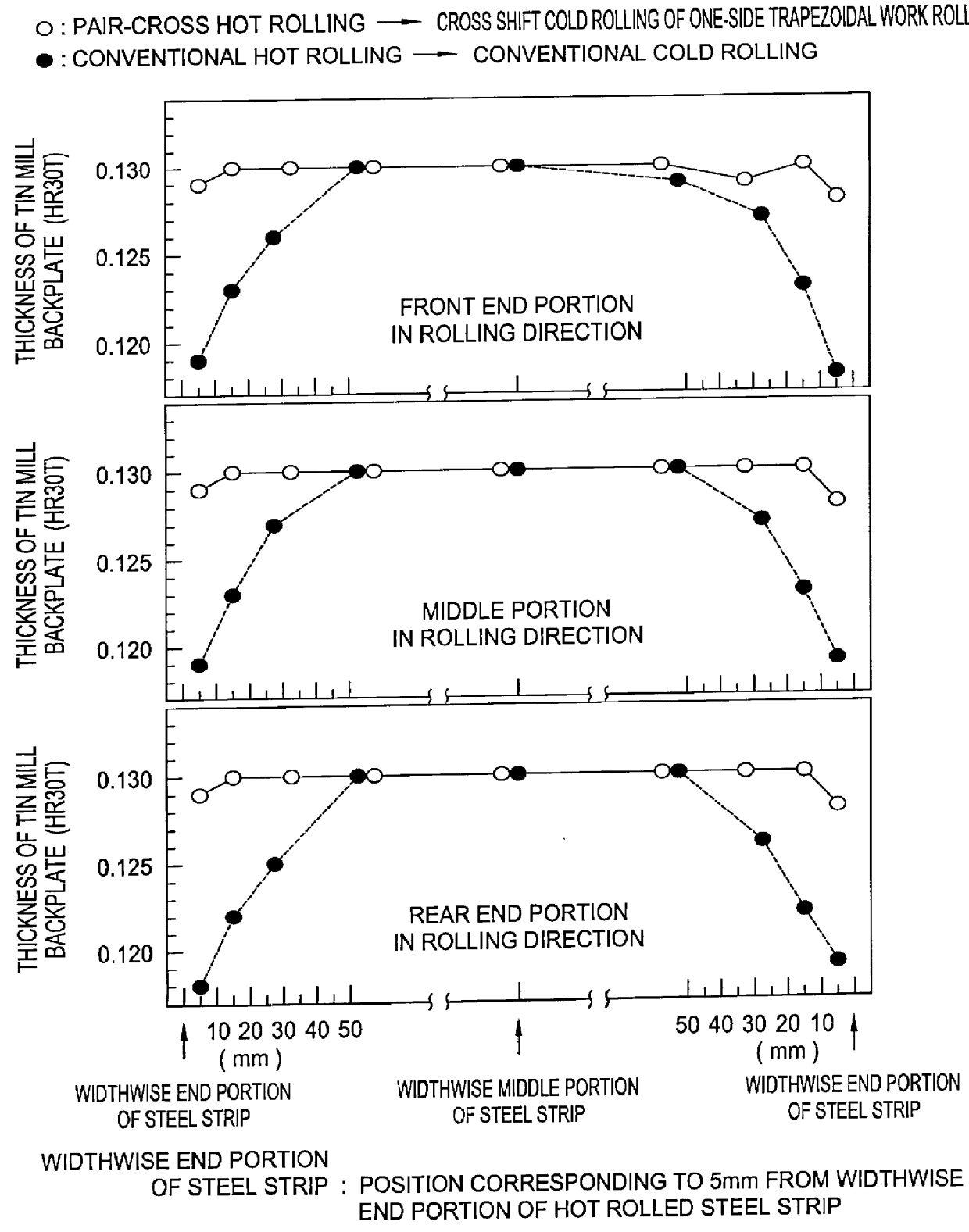
These cast slabs were rough rolled and the resulting sheet bars were joined to a preceding sheet bar and heated at their widthwise end portions by means of an edge heater and continuously rolled by means of a hot finish rolling mill using pair-cross rolls with a changed cross angle at front 3 stands or all 7 stands to form an extremely-thin hot rolled steel strip having a width of 950-1300 mm, which was coiled. Thereafter, it was pickled, descaled and then rolled in a 6 stand tandem continuously cold rolling mill including a cross shift machine using a one-side trapezoidal work roll as a work roll of No. 1 stand to obtain an extremely-thin cold rolled steel strip.

For the comparison, the cast slab was subjected to a hot finish rolling (single rolling) at the conventional cast slab unit and further to a cold roll...

example 4

A cold rolled steel sheet was produced by using steel having achemical composition shown in Table 19 likewise Example 3. A surface-treated steel sheet was produced by subjecting the surface of the steel sheet to a plating and if necessary to reflow treatment and then to a chromate treatment.

The above producing conditions are shown in Table 19 and Table 20. Moreover, the conditions of the plating bath in the Ni fusion treatment and the annealing and various surface treating conditions were the same as in Example 2.

A test specimen was taken out from the thus produced surface treated steel sheet to measure hardness (HR30T) distribution and thickness (mm) distribution in the widthwise direction. And also, r-value (Lankford value) and anisotropy property .DELTA.r thereof were measured.

Moreover, the test conditions of Ni / (Ni+Fe) in the surface layer of Ni diffusion treated material, flatness of the cold rolled steel strip and passing property in the continuous annealing, hardness (HR30T) ...


PUM

PropertyMeasurementUnit
thicknessaaaaaaaaaa
widthaaaaaaaaaa
widthaaaaaaaaaa

Abstract

PCT No. PCT / JP97 / 00826 Sec. 371 Date Nov. 12, 1997 Sec. 102(e) Date Nov. 12, 1997 PCT Filed Mar. 14, 1997 PCT Pub. No. WO97 / 33706 PCT Pub. Date Sep. 18, 1997A steel slab is rough-rolled into a sheet bar and butt-joined onto a preceding sheet bar and a widthwise end portion of the sheet bar is heated by means of an edge heater and then subjected to a continuous finish rolling through pair-cross rolls rolling on at least 3 stands to provide a hot rolled steel strip having a width of not less than 950 mm, a thickness of 0.5-2 mm and a crown within + / -40 mu m, and the hot rolled steel strip is subjected to cold rolling, continuous annealing, temper rolling and, if necessary, plating treatment on the surface of the cold rolled steel strip, whereby there is obtained a steel sheet having an average thickness of not more than 0.20 mm and a width of not less than 950 mm, a thickness variation quantity in a widthwise direction is within + / -4% of the average thickness in a region corresponding to not less than 95% of the width of the steel sheet as cold rolled and a hardness (HR30T) variation in the widthwise direction is within + / -3 of an average hardness.

Description

1. Technical FieldThis invention relates to an extremely-thin steel sheet which can adopt all temper grades of T1.about.T6 and DR8.about.DR10 and is suitable for use in various two-piece cans (SDC: Shallow-Drawn Can, DRDC: Drawn & Redrawn Can, DTRC: Drawn & Thin Redrawn Can, DWIC: Drawing & Wall Ironing Can) or three-piece cans (Side Seam Soldered Can, Side seam Welded Can, Thermoplastic Bonded Side Seam Can) and has uniform material properties and thickness accuracy in spite of extremely-thin thickness and wide-width and is excellent in economy as well as a method of producing the same.In the invention, the term "extremely-thin steel sheet" means both of a blackplate for surface treatment and a surface treated steel sheet.2. Background ArtThe steel sheet for the can is subjected to various platings of Sn [including a tin plated steel having an Sn plated quantity of not less than 2.8 g / m.sup.2 and a thin tin plated steel sheet LTS (Lightly Tin Coated Steel) having an Sn plated quant...

Claims


Application Information

Patent Timeline
Patent Type & Authority Patents(United States)
IPC IPC(8): B21B1/24C21D8/02B21B45/00B21B1/38B21B1/00B21B13/00B21B1/22B21B1/26B21B1/40B21B13/02B21B15/00B21B1/28B21B3/00C21D9/46C21D9/48C22C38/00C22C38/06C22C38/54C25D5/26
CPCB21B1/24C21D8/0226B21B1/26B21B1/28B21B1/40B21B13/023B21B15/0085Y10T428/12972B21B2001/228B21B2001/383C21D8/0278Y10T428/12854Y10T428/12722B21B45/004C22C38/06
Inventor ARATANI, MAKOTORYU, NAOTOSHIKUGUMINATO, HIDEOTOSAKA, AKIOOKUDA, KANEHARUARATANI, MASATOSHIOKADA, SUSUMU
Owner KAWASAKI STEEL CORP
Why Eureka
Try Eureka