Switching type power supply for arc welding

Inactive Publication Date: 2000-04-25
LINCOLN GLOBAL INC
View PDF2 Cites 64 Cited by
  • Summary
  • Abstract
  • Description
  • Claims
  • Application Information

AI Technical Summary

Benefits of technology

Yet another object of the present invention is the improvement, as defined above, which improvement allows the use of a non-dissipative snubber network in a high power, high speed inverter type power supply so that no energy is lost, less heat is generated and the space, cost and complexity of the machines is decreased.
Still a further object of the present invention is the provision of an improvement, as defined above, which improvement is quite simple and can be used on existing two stage or push-pull inverter type power supplies in a manner to reduce the EMI noise and produce a clean signal during actual swit

Problems solved by technology

However, the resonant circuit merely reverses curr

Method used


Image

  • Switching type power supply for arc welding
  • Switching type power supply for arc welding
  • Switching type power supply for arc welding

Examples


Example

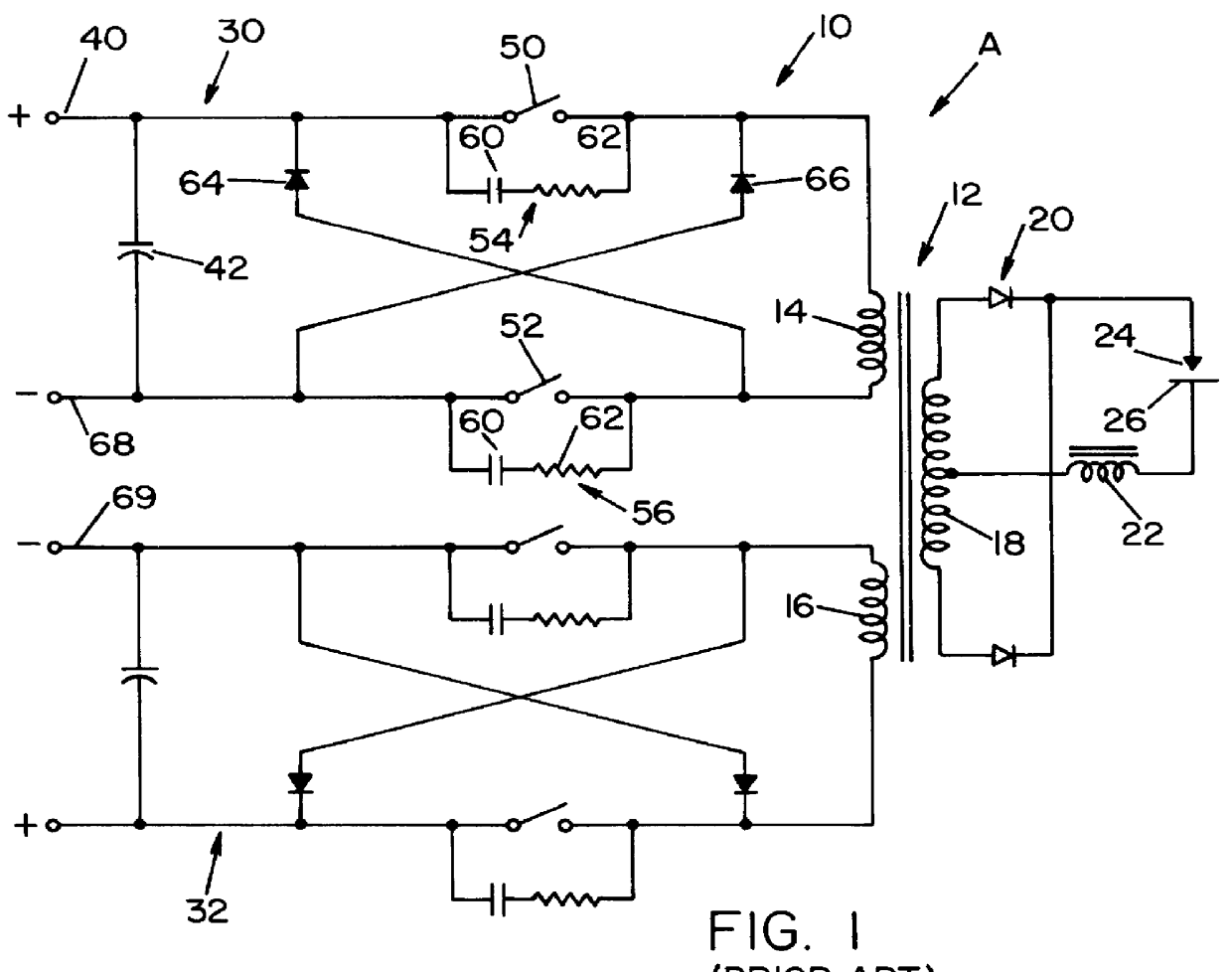
Referring now to the drawings wherein the showings are for the purpose of illustrating a preferred embodiment of the invention only and not for the purpose of limiting same, FIG. 1 shows a prior art electric arc welder A having an inverter type power supply 10 with an output transformer 12 comprising primary winding sections 14, 16 and a secondary winding 18 for driving an output rectifier 20. Inductor or choke 22 controls current flow across electrode 24 and workpiece 26 in accordance with standard practice. Power supply 10 includes a first stage 30 for creating current pulses in winding section 14 and a second stage 32 for creating current pulses in primary winding section 16. Since stages 30,32 are substantially the same, only stage 30 will be described in detail and this description will apply to stage 32. A DC source 40, which is normally the output of a three phase rectifier, has a large filter capacitor 42 maintained at the input voltage during operation of the switches 50, 5...


PUM


Abstract

In a switching type power supply for use in an electric arc welder or plasma cutter, of the type having an output transformer with a primary winding in a series circuit DC source with a selected voltage and a switch, either single or tandem, with a conductive on state to pass a current pulse through the primary winding in a first electrical direction and a non-conductive off state disconnecting the DC voltage source from the winding and a large filter capacitor across the DC input voltage source, the improvement comprising: a snubber network for transferring energy due to the leakage inductance of the primary winding to the filter capacitor when the switch is shifted from the on state to the off state where the snubber network includes a storage capacitor with a diode controlled resonant charging circuit so the winding is in a tank circuit with the storage capacitor to charge the storage capacitor in a charging cycle when the switch shifts from the on state to the off state and a diode controlled discharging circuit where the storage capacitor is in series with the winding and the filter capacitor to discharge the storage capacitor into the filter capacitor when the winding reverses polarity.

Description

The present invention relates to an improved switching type arc welder or plasma cutter with an improved snubber network which transfers leakage energy from the output transformer primary winding to the input power supply during the switching sequence.INCORPORATION BY REFERENCEThe invention relates to a novel passive snubber network that is non-dissipative for combination with high energy rapid switching power supplies, such as inverters. Although this type of snubber network is not known, snubber networks in general of the passive, active, dissipating and non-dissipating are well known and used extensively in switching circuits. The concept of snubbers is found in the May 1993 article by Philip C. Todd entitled Snubber Circuits: Theory, Design and Application. This 1993 article is incorporated by reference herein as background information so that the details of various electrical characteristics of snubber networks need not be repeated. Snubber technology is well developed and know...

Claims


Application Information

Patent Timeline
IPC IPC(8): H02M3/335H02M3/16H02M3/18H02M3/24
CPCH02M1/34H02M3/33523Y02B70/1491Y02B70/1433H02M2001/346H02M1/346Y02B70/10
Inventor CHURCH, LARRY L.LUO, LIFENG
Owner LINCOLN GLOBAL INC
Why Eureka
Try Eureka