Sleep apnea detector system

a detector system and apnea technology, applied in the field of sleep apnea detector systems, can solve the problems of increasing the risk of apnea and respiratory arrest for children, requiring the belt to be affixed, and children and adults receiving epidural narcotics and local anesthetics are particularly vulnerable to apnea, so as to achieve greater sensitivity to events.

Inactive Publication Date: 2000-05-16
ENGINEERED VIGILANCE
View PDF22 Cites 417 Cited by
  • Summary
  • Abstract
  • Description
  • Claims
  • Application Information

AI Technical Summary

Benefits of technology

In various other embodiments, rather than Fourier transform processing, the detector may operate directly on image light, for example by forming an image comprised of a speckle pattern made by the reflected laser light mixed with source light on a video sensor or a charge-coupled device (CCD). In this case, the continuously changing speckle pattern consisting of bright and dark speckles is analyzed by an image analysis protocol which rejects artifacts of local motion represented by localized changes of short duration, such as from twitches and the like, as well as artifacts of abrupt motion representative of major body motions occurring at a rate too fast to be associated with the breath cycle. The remaining slowly evolving patterns of speckle dots are analyzed to develop a general amplitude of breathing cycle motion. In various other embodiments, one or more additional sensors such as acoustic sensors that detect breath sounds can be used to provide additional information and allow differentiation of inhalation and exhalation cycles, as well as greater sensitivity to events such as abrupt airway obstruction. These acoustic signals are then also subject to pattern recognition and linked to the alarm states of the device.

Problems solved by technology

In addition, children are particularly vulnerable to apnea after general anesthesia, and both children and adults receiving epidural narcotics and local anesthetics are at increased risk of apnea and respiratory arrest.
A significant drawback of the strain-sensing belt technique is that it typically requires that the belt be affixed to the patient.
The corresponding wires that couple the belt with the detection unit markedly increase the risk that the subject will become entangled in the wires, which is undesirable, especially with small children.
Moreover, if the subject is experiencing unrestful sleep which is accompanied by tossing and turning, the wires may detach from the unit or the belt, thereby creating false alarms.
A drawback of the remaining techniques is that movement of the subject interferes with the monitoring of the subject.
Consequently, the system may generate false alarms, which are bothersome to the subject and to the attending clinicians in a hospital environment.

Method used


Image

  • Sleep apnea detector system
  • Sleep apnea detector system
  • Sleep apnea detector system

Examples


first embodiment

In yet another embodiment, the illumination source can emit a fairly broadband signal or a chirp containing numerous frequencies. The return signal is then processed by a Fourier transferor, much as in the first embodiment, to detect motion of the chest wall.

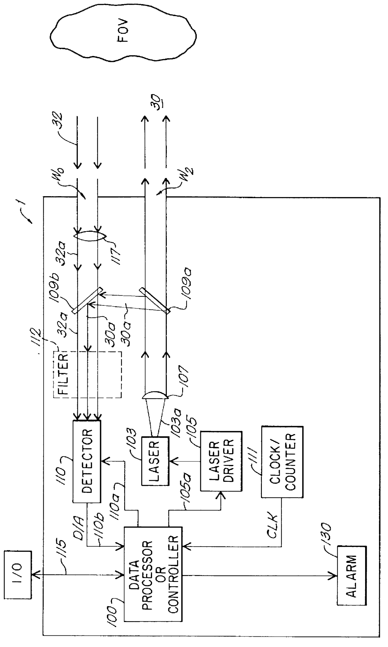
It will be appreciated that when such Doppler processing is used, the optics and optical paths may take a variety of forms corresponding to known Doppler measurement systems. Thus, for example, the collection window W.sub.O can include two sub windows that subtend different angles with respect to the field of view, and the detector may include several detection surfaces for separately detecting the light along each of the two return paths. This allows the receiver circuit to detect movement along separate directions of motion. Furthermore, the two windows W.sub.O, W.sub.L can be replaced by a single window in which a large area, e.g., a 4".times.6" holographic lens, collects the return illumination. Such a lens can be formed wit...

embodiment 200

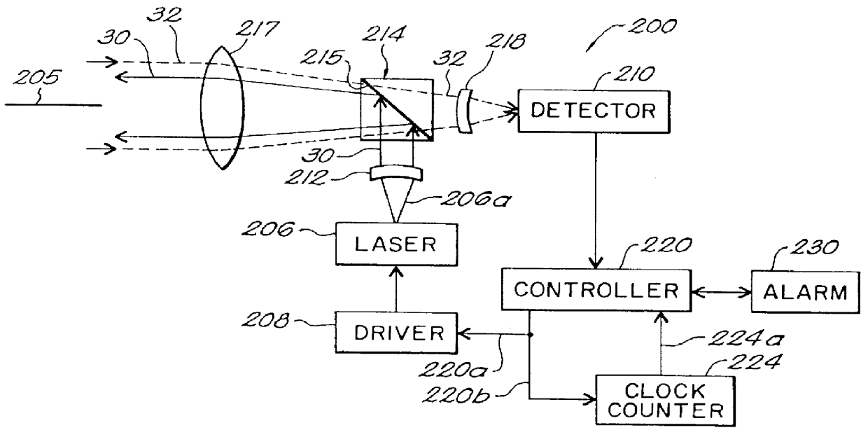
FIG. 2A shows another embodiment 200 of the invention which, like the device of FIG. 2, performs Doppler measurements to detect breathing motions. In this embodiment, the laser illumination beam 30 generated by the laser 206 and the return or reflected light 32 travel along a common optical path or axis, e.g., axis 205, through an objective optics system 217. The objective elements 217 can include one or more lens that collimates the light generated by the laser, and which converges the returning light upon a detector 210. For example, the driver circuit 208 drives the laser 206 to generate laser pulses in response to command signals 220a from the controller 220. According to one practice, the laser 206 is a laser transmitting diode which emits repetitive pulses 206a, for example, 380 pulses per second. Suitable laser diodes for use with this embodiment include gallium-arsenide laser diodes having a wavelength of 905 nm, with a peak power output of 50 watts, and a 30-50 ns pulse wid...


PUM


Abstract

An apnea monitor and system for treatment includes a detector in a fixed console that projects a detection beam at a sleep surface. The detection beam is reflected off a patient on the surface and return light is analyzed to develop a signal which varies with external motion of the patient's upper body. The motion signals are then fed to a pattern recognizer which identifies breath signals and analyzes them to detect cessation or excessive pauses in breathing, and trigger an alarm or intervention to restore breathing regularity. The monitor includes a laser for generating radiation. The radiation is reflected from the patient and is directed onto a detector. The detector produces output signals corresponding to the impinging reflected light, which are processed by a control element to determine the change of movement, e.g., the breathing rate, of the patient.

Description

BACKGROUND OF THE INVENTIONThe present device relates to instruments and systems for detecting apnea and respiratory arrest, and to systems wherein such a detector is used in conjunction with an alarm or a prompt to summon help, jar an individual back to a normal breath cycle, or otherwise respond to or treat the detected condition.Breathing is normally characterized by a more or less regular rhythm of inhaling and exhaling. Apnea, or cessation of respiratory airflow, is a condition in which pauses of greater or lesser duration occur. These pauses may be of such length as to appear to be, or to actually amount to complete cessation of breathing. Apnea may be caused by a number of different mechanisms including obstructive episodes in the upper airway, by neurologic or disease-mediated lack of diaphragmatic motion, or by a combination of these factors. Although poorly understood, sleep apnea has been associated with sudden infant death syndrome (SIDS) which kills hundreds of infants ...

Claims


Application Information

Patent Timeline
Patent Type & Authority Patents(United States)
IPC IPC(8): A61B5/11A61B5/113G01S17/50G01S17/00G01S17/88G01S7/481G06K9/00
CPCA61B5/113A61B5/4818G06K9/00335G01S17/50G01S17/88G01S7/4811G06V40/20
Inventor CORN, STEPHEN B.
Owner ENGINEERED VIGILANCE
Why Eureka
Try Eureka