Spindle assembly for force controlled polishing

a spindle assembly and force control technology, applied in the direction of electric programme control, grinding heads, lapping machines, etc., can solve the problems of reducing the accuracy of position/force measurements, affecting the accuracy of prior art systems, and affecting the accuracy of the prior art system. , to achieve the effect of improving the force resolution capability of the spindle assembly, improving the accuracy of prior art systems, and reducing friction

Inactive Publication Date: 2000-07-04
APPLIED MATERIALS INC
View PDF22 Cites 37 Cited by
  • Summary
  • Abstract
  • Description
  • Claims
  • Application Information

AI Technical Summary

Benefits of technology

In order to improve on the accuracy of prior art systems for providing downforce on a workpiece in a polishing environment, the preferred embodiments described below improve the force resolution capability of the spindle assembly and reduce friction introduced by mechanical linkages in the spindle as

Problems solved by technology

In practice, a certain amount of the pressure applied by the diaphragm piston is lost due to friction losses in the cylinder, bearings, and various other mechanical comp

Method used


Image

  • Spindle assembly for force controlled polishing
  • Spindle assembly for force controlled polishing
  • Spindle assembly for force controlled polishing

Examples


Embodiment Construction

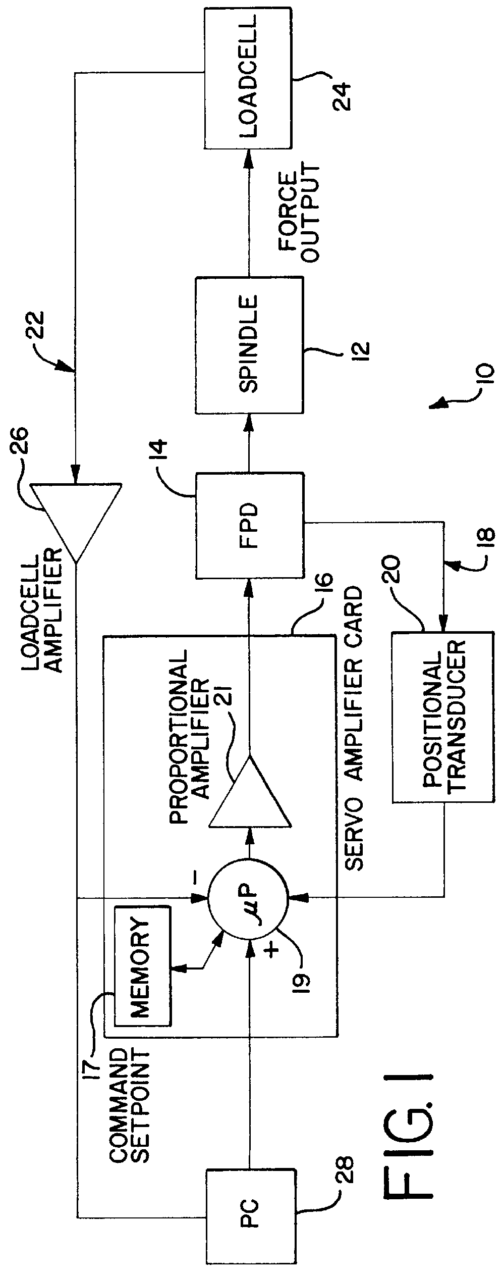
FIG. 1 illustrates a spindle assembly 10 according to a preferred embodiment. The spindle assembly preferably includes a rotatable, axially movable spindle 12. The spindle 12 is axially movable through a bearing assembly (not shown) by a force producing device 14 operatively connected to the spindle 12. In order to both move a workpiece and control the force applied to the workpiece through the spindle 12, the spindle assembly 10 preferably includes two feedback loops in communication with a servo controller 16 that regulates operation of the force producing device 14. The servo controller includes memory 17, a processor 19, and a proportional amplifier 21. A position feedback loop 18 provides information to the servo controller 16 by way of a positional transducer 20 in communication with the force producing device 14. One suitable positional transducer is a glass scale type linear encoder available from RSF of Rancho Cordoba, Calif.

The positional feedback loop is used when the spi...


PUM

PropertyMeasurementUnit
Forceaaaaaaaaaa
Pressureaaaaaaaaaa
Electromagnetismaaaaaaaaaa

Abstract

A spindle assembly for force controlled operation in applications such as the chemical mechanical planarization of semiconductor wafers includes an axially and rotatably movable spindle driven by a force producing device. The force producing device is controlled by a position feedback loop in a first mode of operation and a spindle force control feedback loop in a second mode of operation so that the same force producing device controls spindle movement in the first mode of operation and maintains a constant pressure on a workpiece based on the detected applied pressure in the second mode of operation.

Description

This invention relates to a high performance spindle assembly for forced controlled polishing of metals, plastics, or other materials requiring the application of a constant force. More particularly, the present invention relates to a spindle assembly for force controlled polishing or planarization of semiconductor wafers.Systems for applying force to a workpiece, such as a semiconductor wafer, have in the past measured the pressure applied at the spindle or focused on monitoring the position of the spindle relative to the polishing surface. For example, one version of a spindle assembly for use in polishing a workpiece includes a vertically oriented, spring counter-balanced spindle utilizing a single-acting diaphragm cylinder as a down force mechanism. A pneumatic proportional regulator is used with a built-in pressure transducer feedback loop connected to the diaphragm cylinder in order to control force output of the diaphragm cylinder.In operation, this system lowers the spindle ...

Claims


Application Information

Patent Timeline
IPC IPC(8): B24B49/16B24B37/04B24B41/00B24B41/04G05B19/19G05B19/39B24B41/047B24B37/005B24B49/10
CPCB24B37/005B24B41/044B24B49/16G05B19/39H01L21/304
Inventor SALDANA, MIGUEL A.
Owner APPLIED MATERIALS INC
Why Eureka
Try Eureka