High current welding power supply

a high-current welding and power supply technology, applied in welding equipment, arc welding equipment, manufacturing tools, etc., can solve the problems of high voltage, high cost, and distinct disadvantage of using inverter-based power supply for high welding current, and achieve the effect of easy adjustmen

Inactive Publication Date: 2000-08-29
LINCOLN GLOBAL INC
View PDF8 Cites 172 Cited by
  • Summary
  • Abstract
  • Description
  • Claims
  • Application Information

AI Technical Summary

Benefits of technology

In accordance with another aspect of the invention, improved power supply can be used to create a single polarity pulse or, alternating polarity pulse. Thus, the welder has a DC negative mode, a DC positive mode or an AC mode. In all modes, the inverter stage is turned off, allowing a decay in the maximum current to a lower, selected current value at which time the current pulse is terminated by opening the switch creating the current pulse. Since the rate of reversing polarity in the AC mode of operation determines the frequency of the AC welding operation, a voltage controlled oscillator or similar software programming is used to change the welding pulse frequency; but, the same frequency is us

Problems solved by technology

This architecture for creating an AC welding process has proven quite successful; however, when the welding current is high, i.e. over about 200 amperes, the snubbers in parallel with the first and second transistor based switches are very expensive and quite large.
This was a distinct disadvantage of using the inverter based power supply for high welding currents.
It was found that switching high weld

Method used


Image

  • High current welding power supply
  • High current welding power supply
  • High current welding power supply

Examples


Embodiment Construction

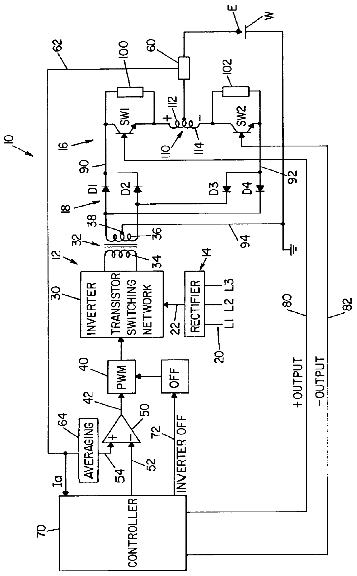
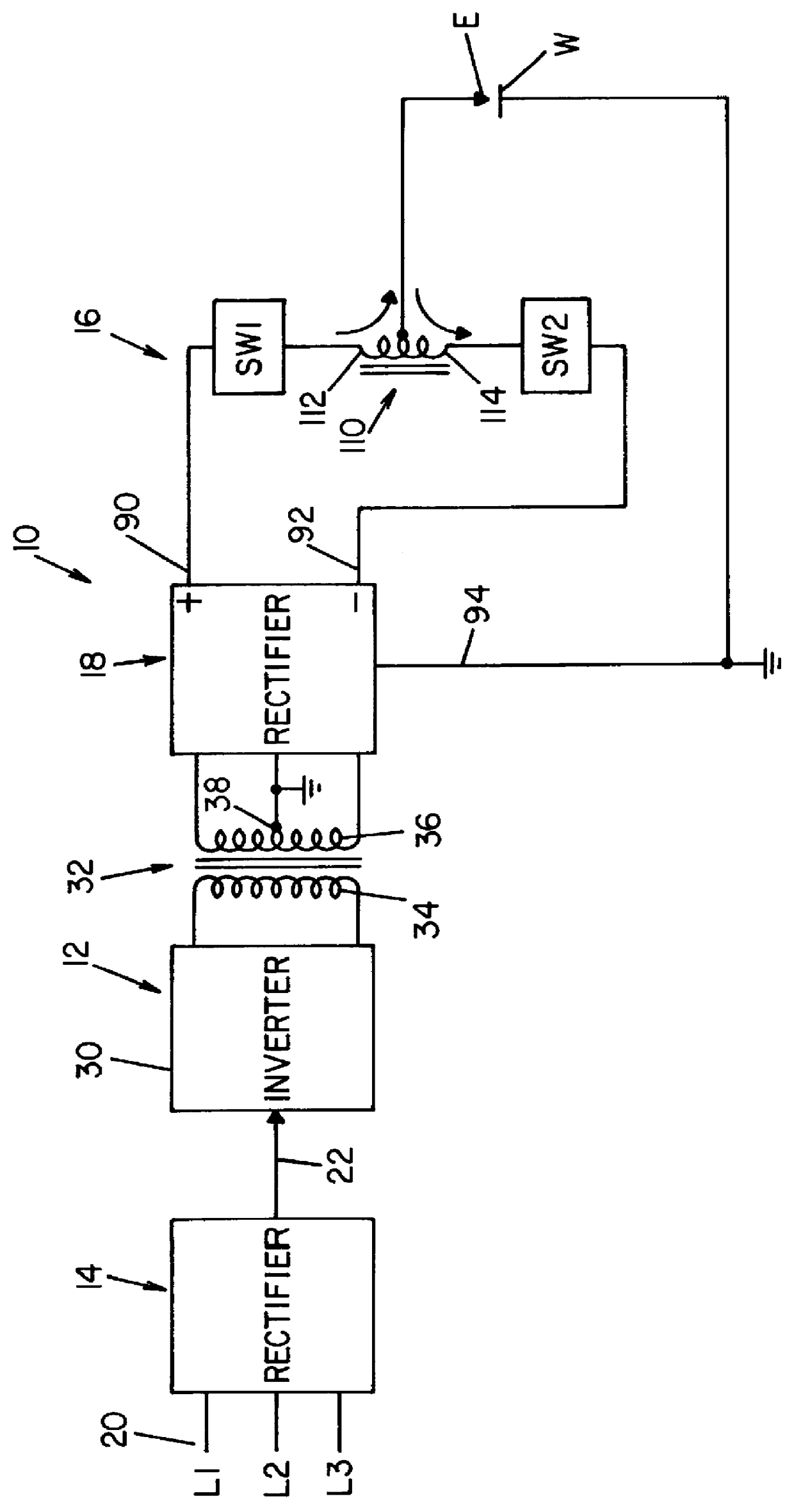
Referring now to the drawings wherein the showings are for the purpose of illustrating the preferred embodiment only and not for the purpose of limiting the same, FIGS. 1 and 1A show an AC welding supply 10 for passing an alternating current through electrode E and grounded workpiece W. Power supply 10 utilizes a standard inverter stage 12 having a rectifier input 14 and adapted to provide DC current at high levels to output switching network 16, which output network creates the current pulses of power supply 10 for performing a welding operation at workpiece W. To provide DC output terminals forming the input of network 16, a full wave rectifier 18 is connected to the inverter stage so the multi-phase input voltage to rectifier 14 is converted to a DC current source having a high maximum current level exceeding 200 amperes and preferably as high as 1000-1200 amperes.

Inverter stage 12 is somewhat standard in architecture and includes an AC input 20 shown as a multi-phase power suppl...


PUM

PropertyMeasurementUnit
Currentaaaaaaaaaa
Currentaaaaaaaaaa
Currentaaaaaaaaaa

Abstract

In a welding power supply for creating welding current in a succession of current pulses with a maximum current level and a trailing off state which current pulses passing through a series circuit including an inductor and electrode in welding relationship with a workpiece wherein the power supply has (a) an inverter stage with an input to be connected to a power source, a first terminal at a first electrical polarity when the inverter is on, a second terminal at a second electrical polarity when the inverter is on, and a control to generate an off signal to turn the inverter off and remove current from the terminals to shift said current pulse toward an off state; and, (b) a power switching stage including a transistor based switch having a conduction condition passing current from the first terminal upon creation of a first logic signal and a non-conduction condition blocking current upon creation of a second logic signal, the improvement comprising: a sensor for measuring the instantaneous value of the welding current, a comparator for producing a low current signal when the instantaneous current is at a selected value substantially below the maximum current level and a circuit or program for creating the second logic signal upon production of a low current signal after generation of an off signal whereby the transistor based switch is switched from the conduction condition to the non-conduction condition when the welding current is generally at the selected value.

Description

The present invention relates to electric arc welding and more particularly to an improved welding power supply for creating a high welding current in a succession of current pulses.INCORPORATION BY REFERENCEThe present invention utilizes an inverter of the transistor switching type for converting a three phase input power source to a load coupling transformer from which the AC output of the inverter can be rectified to create current flow between the electrode and workpiece of a welding operation. Such inverters employ a pulse width modulator operated at over 18 kHz for controlling the magnitude of the welding current flowing through the welding operation. These inverters are well known in the art and are generally shown in Blankenship U.S. Pat. No. 5,349,157 and Blankenship U.S. Pat. No. 5,351,175. These patents are incorporated by reference herein as background information illustrating a three phase inverter with current controlled by a high frequency pulse width modulator direct...

Claims


Application Information

Patent Timeline
IPC IPC(8): B23K9/09B23K9/10B23K9/06B23K9/073
CPCB23K9/091B23K9/1043B23K9/1062H04M3/42289H04M7/0066H04M7/1205
Inventor STAVA, ELLIOTT K.
Owner LINCOLN GLOBAL INC
Why Eureka
Try Eureka