Method of ion fragmentation in a quadrupole ion trap

Inactive Publication Date: 2000-09-26
THERMO FINNIGAN
View PDF2 Cites 52 Cited by
  • Summary
  • Abstract
  • Description
  • Claims
  • Application Information

AI Technical Summary

Benefits of technology

It is an object of the present invention to provide a method of collisionally inducing dissociation in an ion trap with improved performance.
The present invention relates to a method of collisionally inducing ion fragmentation in an ion trap which includes the steps of applying an excitation voltage to the ion trap whose amplitude is substantially linearly related to the mass-to-charge ratio of the ion to be fragmented for a particular instrument, and to calibrating the substantially linear relationship on a per instrument basis with a simple and fast calibration process.

Problems solved by technology

The fact that different ions require different excitation voltage amplitudes precludes the ability of doing automated experiments where the choice of parent ion is not predetermined but made in real time in a chromatographic or other fast time scale.
Under these circumstances, tuning of the voltage amplitude is not practical, since in general it is a time-consuming process.
In addition to this limitation, the particular setting of resonance excitation voltage amplitude required to fragment a given ion optimally can differ from one instrument to another.
Consequently, the same excitation voltage amplitude used on multiple instruments may not give identical results.

Method used


Image

  • Method of ion fragmentation in a quadrupole ion trap
  • Method of ion fragmentation in a quadrupole ion trap
  • Method of ion fragmentation in a quadrupole ion trap

Examples


Embodiment Construction

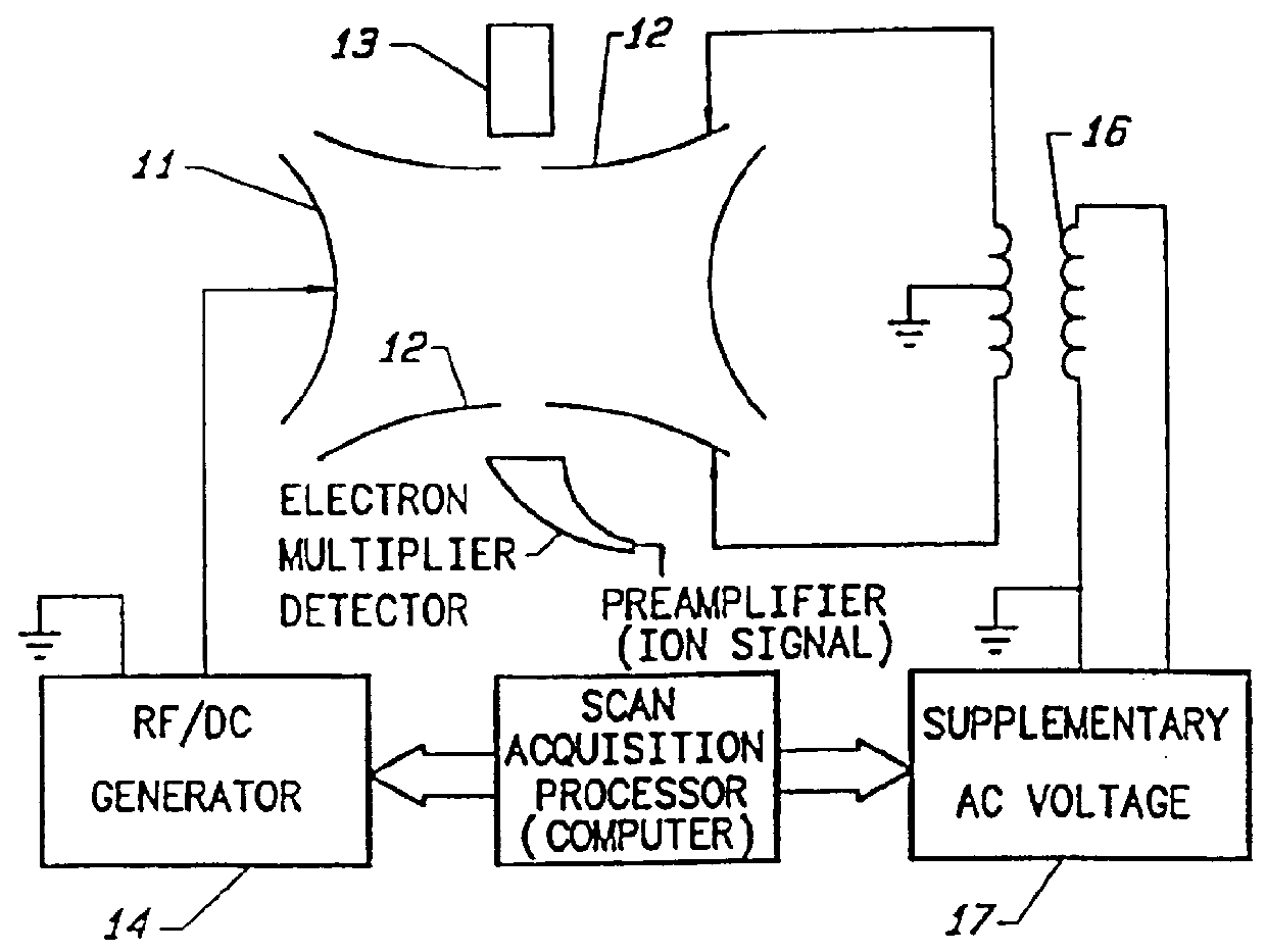
Referring to FIG. 1, there is schematically illustrated a quadrupole ion trap which includes a ring electrode 11, spaced end caps 12, and an electron gun 13 for ionizing samples introduced into the trap as, for example, from a gas chromatograph or other sample source (not shown). Alternatively, the electron gun 13 may be an external ionizer (ionization source) that injects externally formed sample ions into said trap. In the following description, both methods are referred to as introducing ions into the ion trap. Suitable voltages are applied to the ring electrode 11 via the amplifier and r.f. / DC generator 14. The trap preferably contains a collision or damping gas as described in U.S. Pat. Nos. 4,540,884 and RE34000. Excitation or ejection voltages are applied across the end caps 12 from the supplementary AC voltage generator 17 to the transformer 16 whose secondary is connected across the end caps. A scan acquisition processor (computer) controls the application and amplitude of ...


PUM


Abstract

There is described a method of generating product ions in a quadrupole ion trap in which the amplitude of the applied excitation voltage for an ion of a given mass-to-charge ratio (m / z) is linearly related to its mass-to-charge ratio (m / z).

Description

This invention relates generally to a method of ion fragmentation in a quadrupole ion trap and more particularly to a method in which the selected excitation energy for an ion of given mass-to-charge ratio is substantially linearly related to its mass-to-charge ratio (m / z).In U.S. Pat. No. 4,540,884 there is described a method of mass analyzing a sample by the use of a quadrupole ion trap. Basically, a wide range of ions of interest are created in or stored in an ion trap during an ionization step. In one method, the r.f. voltage applied to the ring electrode of the quadrupole ion trap is then increased and trapped ions of consecutively increasing specific mass-to-charge ratio (m / z) exit the ion trap. These ions are detected to provide an output signal indicative of the masses of stored ions.In U.S. Pat. No. 5,420,425, there is described an ion trap mass spectrometer for analyzing ions, and more particularly a substantially quadrupole ion trap mass spectrometer with an enlarged ion ...

Claims


Application Information

Patent Timeline
IPC IPC(8): H01J49/42H01J49/34G01N27/62
CPCH01J49/0009H01J49/0063H01J49/424
Inventor SCHWARTZ, JAE C.TAYLOR, DENNIS M.
Owner THERMO FINNIGAN
Why Eureka
Try Eureka