Short-circuit microstrip antenna and device including that antenna

a microstrip antenna and short-circuit technology, applied in waveguide devices, substantially flat resonant elements, resonant antennas, etc., can solve the problems of increasing the manufacturing cost of the connecting line described in the above article, limiting the radiation power intercepted by the body of the user of the device, and unable to connect the antenna to the transmitter on its own

Inactive Publication Date: 2000-10-17
WSOU INVESTMENTS LLC
View PDF3 Cites 120 Cited by
  • Summary
  • Abstract
  • Description
  • Claims
  • Application Information

AI Technical Summary

Benefits of technology

facilitating the coupling between a short-circuit antenna of the above kind and a signal processing unit such as a transmitter that has to cooperate with the antenna, and

Problems solved by technology

In the case of a mobile telephone, the continuous nature of the bottom ground layer of the antenna means that the radiated power intercepted by the body of the user of the device is easily limited.
A first drawback relates to the fact that the strip and the ground of the connecting line are respectively in line with the patch and with the ground of the antenna.
As a result the connecting line described in the above article cannot on its own connect the antenna to the transmitter.
An additional connecting line must be provided and installing two such lines in a device of the above kind increases its manufacturing cost.
Another drawback of the above antenna is that it can be fed, or more generally coupled to the signal processing unit, only when various parameters are adjusted precisely.
In the case of industrial mass production of such antennas, this adjustment problem can increase manufacturing costs unacceptably.
The second prior art antenna has the drawback that providing an efficient coupling device using the terminal part of the central conductor of a coaxial line connected to the antenna patch requires a hole through the substrate and leads to practical difficulties, in particular with adjusting the position of the connection point.
These problems increase the cost of manufacture, especially in the case of mass production.
The above antenna has the disadvantage of a non-negligible impedance discontinuity at the connection between the first waveguide and the coaxial cable or the second microstrip waveguide.

Method used


Image

  • Short-circuit microstrip antenna and device including that antenna
  • Short-circuit microstrip antenna and device including that antenna
  • Short-circuit microstrip antenna and device including that antenna

Examples


Embodiment Construction

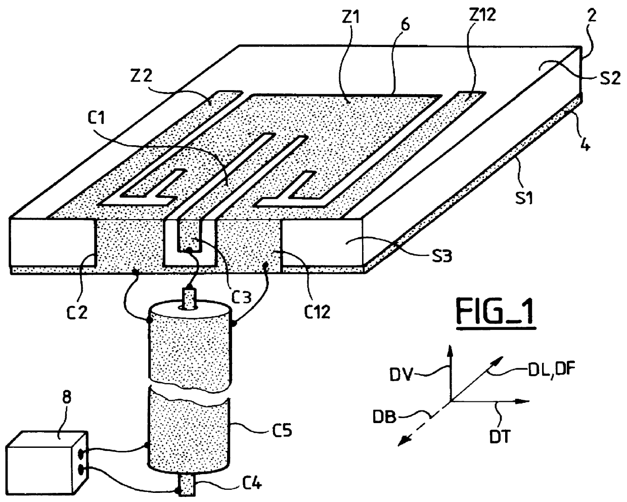
Like the first above-mentioned prior art antenna, an antenna in accordance with the present invention has a resonant structure made up of the following components:

A dielectric substrate 2 having two mutually opposed main surfaces extending in directions defined in the antenna and constituting horizontal directions DL and DT, these directions possibly depending on the area of the antenna concerned. As previously explained the substrate can have various shapes. Its two main surfaces are respectively a bottom surface S1 and a top surface S2. Another direction is also defined in the antenna. It is at an angle to each of the horizontal directions and constitutes a vertical direction DV. The angle just referred to is typically a right angle. However, the vertical direction can also be at different angles to the horizontal directions and can also depend on the area of the antenna concerned. The substrate has several edge surfaces, like the surface S3, each of which connects an edge of the ...


PUM


Abstract

A microstrip antenna includes a composite short-circuit consisting of two conductive strips. A vertical strip, in the plane of the short-circuit between the two strips, is connected to the central conductor of a coupling line forming part of the antenna and enabling the coupling with a resonance thereof, as for example to excite such resonance. The short-circuit and the vertical strip constitute two terminals for said antenna, enabling it to be easily connected to a signal processing units, such as a transmitter. The antenna described includes two zones enabling it to operate at two frequencies. The antenna has particular utility in portable telephones and their base stations.

Description

The present invention concerns microstrip antennas.These antennas are typically used at microwave frequencies and at radio frequencies. The antenna includes a patch that is typically obtained by etching a metallic layer. It is known as a microstrip patch antenna.The microstrip technique is a planar technique with applications to making signal transmission lines and to making antennas constituting a coupling between such lines and radiated waves. It employs conductive patches and / or strips formed on the top surface of a thin dielectric substrate which separates them from a conductive ground layer on the bottom surface of the substrate. A patch of the above kind is typically wider than a strip of the above kind and its shape and dimensions constitute important characteristics of the antenna. The substrate is typically in the form of a rectangular plane sheet of constant thickness. This is in no way obligatory, however. In particular, it is known that an exponential variation in the th...

Claims


Application Information

Patent Timeline
Patent Type & Authority Patents(United States)
IPC IPC(8): H01Q9/04H01P5/08H01Q1/24H01Q21/30H01P11/00H01Q13/08
CPCH01P5/08H01Q1/24H01Q9/045H01Q9/0421H01Q9/0407
Inventor GRANGEAT, CHRISTOPHEKOUAM, CHARLES NGOUNOULORCY, LAURENCECOUPEZ, JEAN-PHILIPPELEPENNEC, FRANCOISTOUTAIN, SERGE
Owner WSOU INVESTMENTS LLC
Why Eureka
Try Eureka