Steam cooling type gas turbine combustor

a gas turbine and steam cooling technology, which is applied in the direction of machines/engines, mechanical equipment, light and heating apparatus, etc., can solve the problems of increasing the difficulty of improving the capacity of the gas turbine and reducing the emission of no.sub.x, reducing the thermal efficiency of the turbine, and reducing the temperature of the flow

Inactive Publication Date: 2000-12-26
TOHOKU ELECTRIC POWER +1
View PDF4 Cites 27 Cited by
  • Summary
  • Abstract
  • Description
  • Claims
  • Application Information

AI Technical Summary

Problems solved by technology

However, if air is used to cool the turbine, the air used for cooling and the air that leaks from the cooling channels is released into the main gas flow.
This air makes it more difficult to improve the capacity of the gas turbine and decrease the emission of NO.sub.x.
However, if the steam, which has been used to cool the hot portions of the turbine in a combined power plant, is released into the main gas flow, the temperature of the flow will drop, and the thermal efficiency of the turbine will decrease.
Although the use of steam instead of air as the cooling medium in the combustor of a gas turbine has been given a great deal of consideration, it is still at the conceptual level and has not yet been put into practice.
One reason for this is because it can be difficult to create steam-cooling channels in a combustor wall, which has complex forms, especially by a conventional laser or electrospark machining.
This demands a strong enough structure for forming the steam channels, but in fact, there is no actual structure for such a steam-cooling to fulfil this demand in the market.
In addition to this requirement, it is also important not to allow leakage of the steam from the steam system.
It is, however, not easy to fulfil all of these requirements because of structural reasons.
This made it difficult to make such a steam-cooled combustor in the actual market.
It is naturally not practical to use the same structure and the same concept used for an air-cooled combustor as a steam-cooled combustor, because it does not fulfil the requirements for steam-cooled combustor.

Method used


Image

  • Steam cooling type gas turbine combustor
  • Steam cooling type gas turbine combustor
  • Steam cooling type gas turbine combustor

Examples


Embodiment Construction

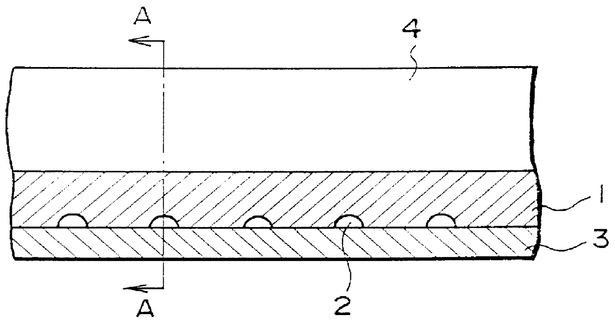
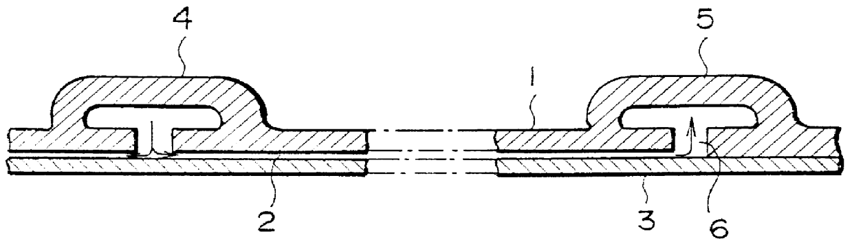
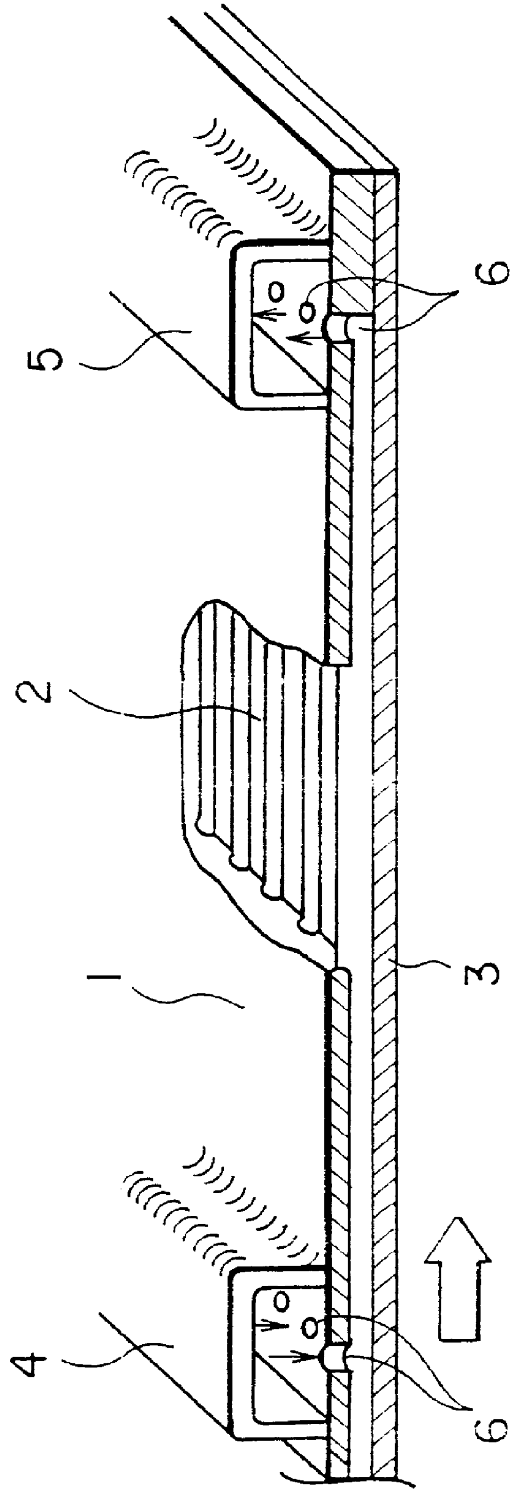
In this section a detailed explanation of several preferred embodiments of this invention will be given with reference to the drawings. To the extent that the dimensions, materials, shape and relative position of the components described in this embodiment are not definitely fixed, the scope of the invention is not limited to those specified, which are meant to serve merely as illustrative examples.

In a gas turbine plant, several combustors of the sort described earlier, with a combustion nozzle 51 on the gas inlet side of combustion chamber 50, as shown in FIG. 5, and a tailpipe 52 on the gas outlet side, are provided inside a cylindrical casing (not shown). The casing is pressurized using compressed air from a compressor. These combustors are arranged around the circumference of the casing. The combustion gases generated in chamber 50 are conducted to the turbine via tailpipe 52 and used to drive the turbine.

As can be seen in FIG. 5, the combustor, which is a preferred embodiment ...


PUM


Abstract

PCT No. PCT/JP98/00552 Sec. 371 Date Apr. 29, 1999 Sec. 102(e) Date Apr. 29, 1999 PCT Filed Feb. 12, 1998 PCT Pub. No. WO98/36220 PCT Pub. Date Aug. 20, 1998This invention concerns the use of pressurized steam as the cooling medium in the combustor wall of a gas turbine combustor. It is distinguished by the following. The combustor wall is configured by 1) a plurality of cooling channels for cooling steam, sealed by an exterior wall panel and a heat-resistant plate which are assembled by soldering or some other method; 2) a supply manifold for supplying the cooling steam into the cooling channels, which is provided on one end of the cooling channels; and 3) a recovery manifold for recovering the cooling steam from the cooling channels, which is provided on another end of the cooling channels. This arrangement can form strong enough steam-channels that do not allow any leakage of the high pressure steam from the cooling system.

Description

INDUSTRIAL FIELDThis invention concerns a steam-cooled combustor for a gas turbine. More specifically, it concerns a structure for steam-cooling the exterior wall panels of the combustor, which are exposed to very hot combustion gases.TECHNICAL BACKGROUNDOne effective way to improve the thermal efficiency of a gas turbine is to boost the temperature at the gas inlet of the turbine. It is also desirable to suppress increased emission of NO.sub.x from the combustor, which supplies combustion gases to the turbine, and to improve the heat resistance of the turbine and its cooling capacity.Since the combustor is exposed to temperatures of 1500 to 2000.degree. C., it must be properly cooled so that the temperature of its exterior wall panels remains in the allowable range as it experiences thermal stress.Generally, combustors in gas turbines are cooled by running the air to be used for combustion along their inner wall panels, and by forcing air inside these wall panels in order to cool t...

Claims


Application Information

Patent Timeline
Patent Type & Authority Patents(United States)
IPC IPC(8): F23R3/00F02C7/141F02C7/18F23M5/08
CPCF23R3/005F05B2260/205F05B2260/233
Inventor IGARASHI, KIRYOOGOSE, AKIOAKAGI, KOUICHIINADA, MITSURU
Owner TOHOKU ELECTRIC POWER
Why Eureka
Try Eureka