
Rock bit face seal having anti-rotation pins

Inactive Publication Date: 2001-01-23
REEDHYCALOG LP
View PDF19 Cites 31 Cited by
  • Summary
  • Abstract
  • Description
  • Claims
  • Application Information

AI Technical Summary

Benefits of technology

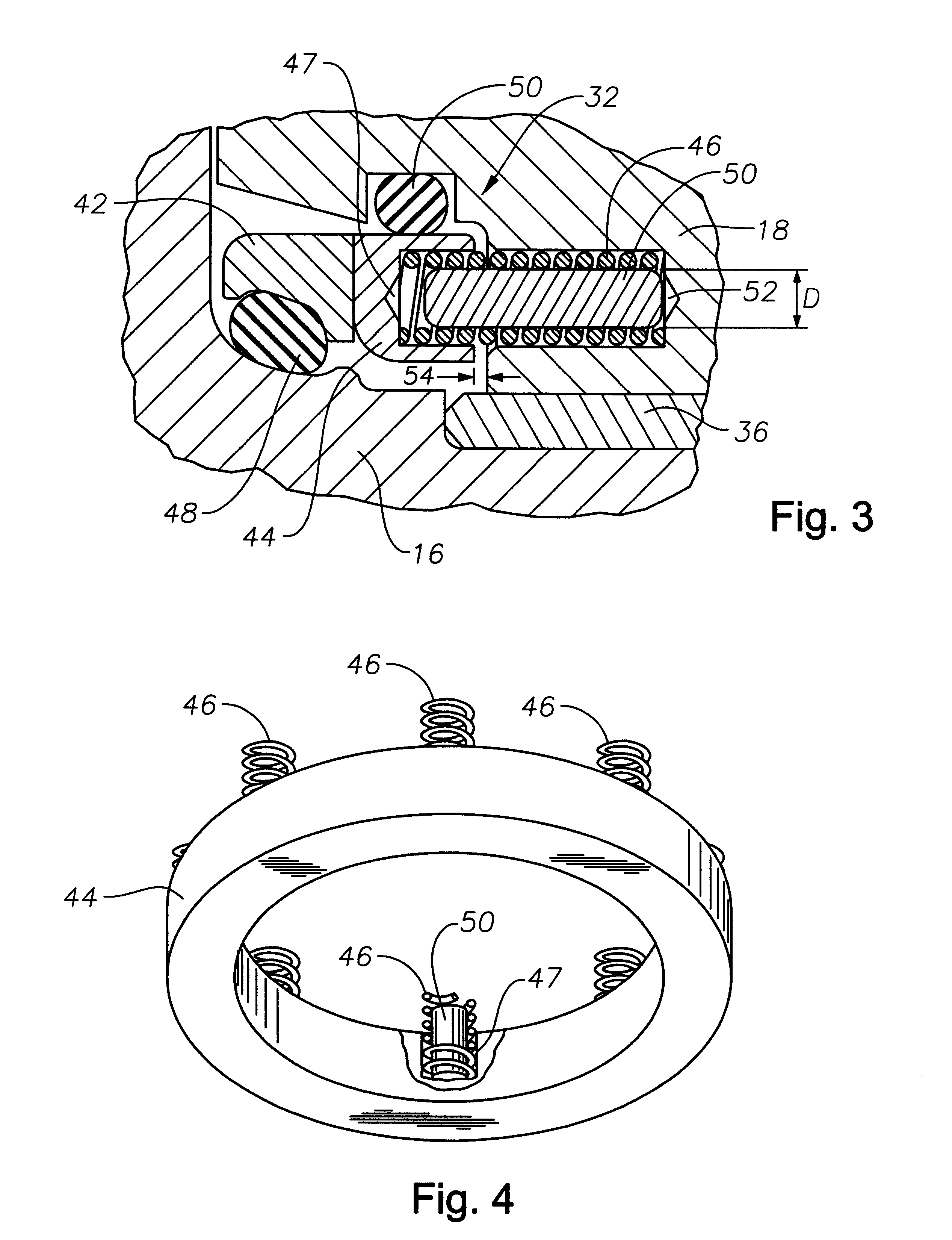
The present invention provides a rigid face seal for rotary rock bits with a novel coil spring energization system that prevents yielding of the coil springs in extreme torque conditions. Within at least one of the coil springs is a cylindrical pin designed to co-act with the spring such that the combination becomes very stiff in the radial direction as the spring extends beyond a certain amount. This prevents the high torque from yielding the springs. When the spring returns to its normal extension, the pin does not interfere with the axial compression of the spring. This combination allows the coil spring energizers of a rotary rock bit rigid face seal to survive the occasional extreme torque event.
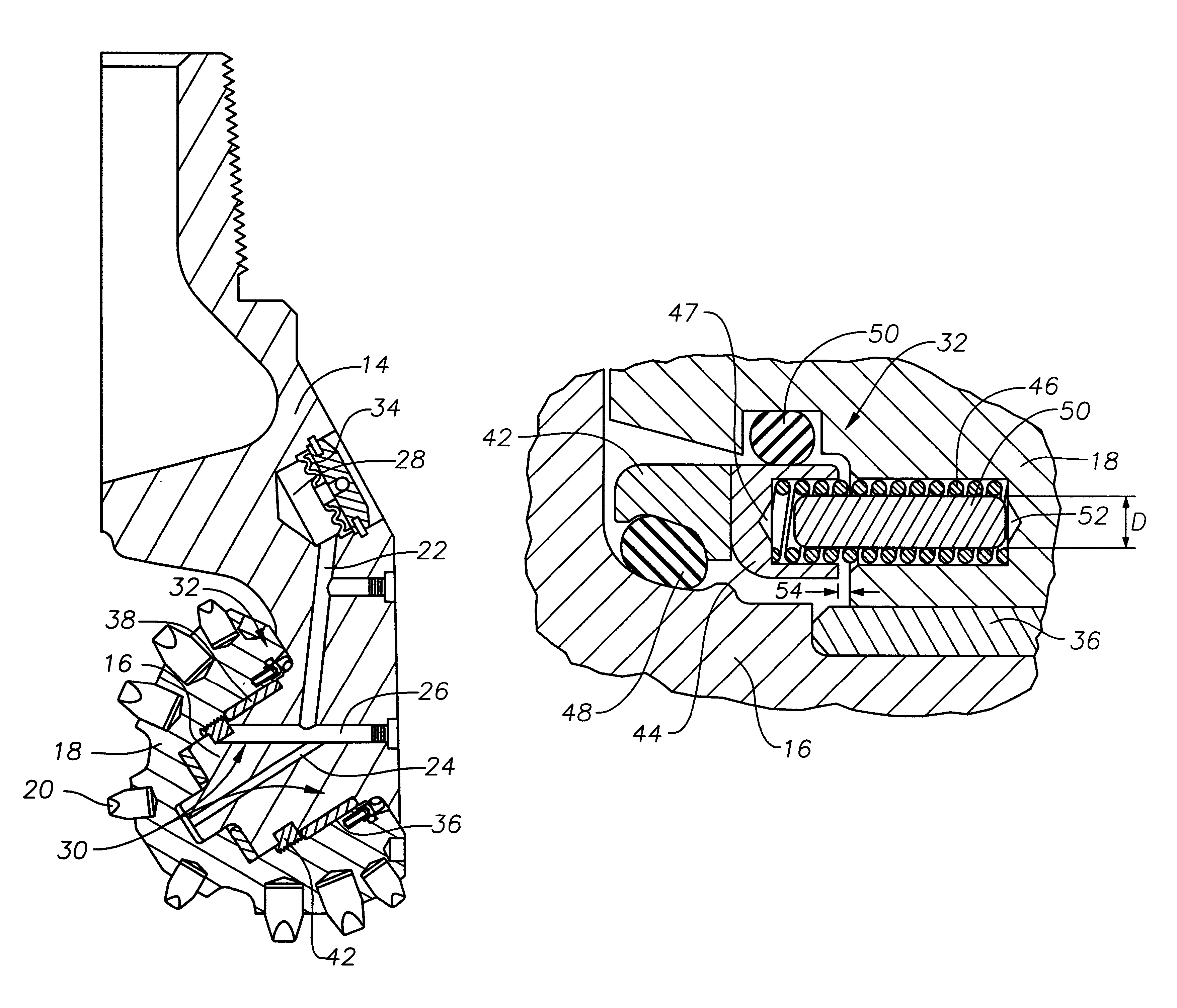
In its broadest form the invention is a rolling cutter rock drill bit for drilling boreholes into the earth with at least one rolling cutter mounted upon a cantilevered bearing shaft. A lubricant is disposed between the rolling cutter and the cantilevered bearing shaft. A rigid face seal assembly is mounted between the rolling cutter and the bearing journal to seal the lubricant within the rolling cutter. The rigid face seal assembly is made with at least one rigid seal ring and a plurality of coil spring energizers disposed upon the seal ring. A cylindrical pin is disposed within one or more of the coil spring energizers. The outside diameter of the pin is just slightly smaller than the inside diameter of the coil spring when the face seal is assembled at equilibrium. This allows the spring and the pin to be independent of each other. However, when the spring extends and the torque on the seal faces increase, the pin and spring co-act to become stiff and transmit very high torques without damage to the coil spring.

Problems solved by technology

Mechanical rigid face seals have become the seal of choice for rock bits used in the most severe drilling environments, due to the operating limitations of elastomers as dynamic seals.
Oftentimes in operation, however, the film becomes too thin and frictional contact between the sealing faces will cause high torques on the seal faces.
These high torques can cause failure of the systems which hold the seal in place.
For instance, if elastomeric energizers are transmitting the torque, they may slip.
A small amount of slippage can cause excessive wear on the elastomer energizers, leading to an early failure.
Even when coil spring energizers, such as shown in U.S. Pat. No. 4,838,365, are transmitting the torques, it is possible, under some circumstances for the coil spring energizers to fail.
When the operating torques become too high, the shear forces on the coil springs can cause them to yield.
Once any one of the springs yield, the seal assembly loses its ability to move in response to volume changes in the lubricant near the seal, leading to rapid seal failure.
However, the diverging design requirements of the two groups tend to make them non-analogous.
It is undesirable in these designs for the springs to carry any part of the face torque because torque loading can profoundly affect the springs' ability to energize the seal faces.
This happens because the pressure force on the seal face during an `onward loading` volume compensating event causes the springs to extend and also causes the axial face load to increase.
However, it has been observed that face torques may sometimes exceed 200 inch-pounds in these bits.
The coil spring is vulnerable to yielding only when it is extended enough to leave one loop of the coil unsupported.
Because the coil spring often extends enough to leave a coil loop unsupported, the torque on the seal faces transmitted through the coil springs can cause the coil springs to yield.
However, when the spring extends and the torque on the seal faces increase, the pin and spring co-act to become stiff and transmit very high torques without damage to the coil spring.

Method used


Image

  • Rock bit face seal having anti-rotation pins
  • Rock bit face seal having anti-rotation pins
  • Rock bit face seal having anti-rotation pins

Examples


Embodiment Construction

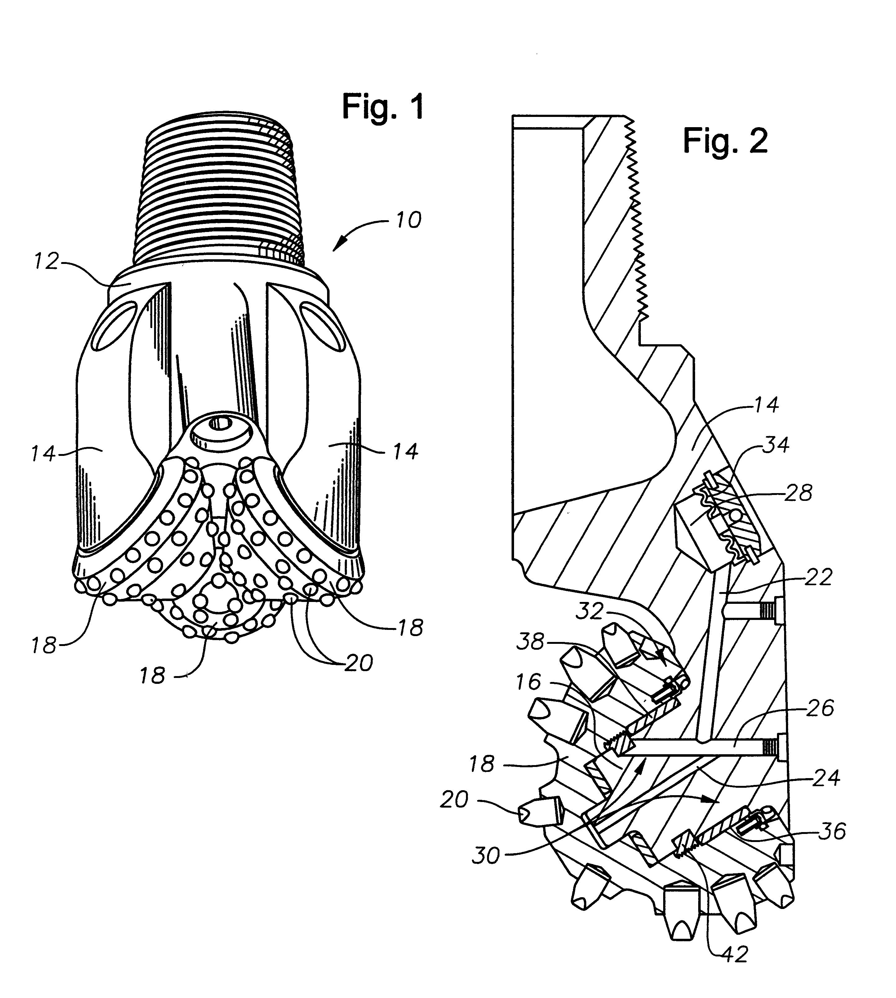
Referring now to the drawings in more detail, and particularly to FIGS. 1 and 2. A rolling cutter rock drilling bit 10 includes a body 12 with a plurality of leg portions 14. A rolling cutter rock drilling bit 10 is also commonly called a rock bit, a rolling cutter drill bit or an oilfield drill bit. A cantilevered bearing shaft 16 formed on each leg 14 extends inwardly and downwardly. A rolling cutter 18 is rotatably mounted upon the shaft 16. Attached to the rolling cutter 18 are hard, wear resistant cutting inserts 20 which engage the earth to effect a drilling action and cause rotation of the rolling cutter 18. A friction bearing member 36 is mounted between the bearing shaft 16 and a mating bearing cavity 38 formed in the cutter 18. This friction bearing 36 is designed to carry the radial loads imposed upon the cutter 18 during drilling. A retention bearing member 42 is mounted in the cutter 18 to retain the cutter 18 upon the bearing shaft 16 during drilling.

Internal passagewa...


PUM


Abstract

The invention provides a mechanical face seal for rotary rock bits with a novel coil spring energization system that prevents yielding of the coil springs in extreme torque conditions. Within at least one of the coil springs is a cylindrical pin designed to co-act with the spring such that the combination becomes very stiff in the radial direction as the spring extends beyond a certain amount. This prevents the high torque from yielding the springs. When the spring returns to its normal extension, the pin does not interfere with the axial compression of the spring. This combination allows the coil spring energizers of a rotary rock bit mechanical face seal to survive the occasional extreme torque event.

Description

1. Field of the InventionThis invention provides an enhanced rotary face seal for roller cone rock bits. The new seal has pins which positively prevent rotation of the seal ring with respect to the seal ring carrier.2. Description of the Related ArtModern, premium roller cone rock bits utilize sealing systems to prevent the loss of lubricant from the roller cones. The seal system also prevents the abrasive laden drilling fluid outside the bit from entering into, and failing the bearing system of the rolling cones.There are two basic types of sealing systems in common use in rolling cutter drill bits. In most drill bits, an elastomeric packing ring provides the seal between the rolling cone and the bearing system. These bits utilize an elastomeric compression type sealing system, and have adequate performance in most drilling applications. For rock bits used in very severe bit applications, however, rotary mechanical face seals are disposed between the rolling cone and the bearing to...

Claims


Application Information

Patent Timeline
IPC IPC(8): E21B10/08E21B10/22E21B10/25
CPCE21B10/25
Inventor BURR, BRUCE HAWLEY
Owner REEDHYCALOG LP
Learn More