Method for selectively coupling layers of a stator in a motor/generator

a technology of stators and layers, applied in the direction of magnetic circuits characterised by magnetic materials, magnetic circuit shapes/forms/construction, magnetic circuit rotating parts, etc., can solve the problems of reduced performance, material strength, and limited flux through which each winding half moves through the flux of the produced flux

Inactive Publication Date: 2001-01-30
SMITH TECH DEV LLC +1
View PDF9 Cites 52 Cited by
  • Summary
  • Abstract
  • Description
  • Claims
  • Application Information

AI Technical Summary

Benefits of technology

The motor / generator also has a stator that includes a layer of conductors or windings between each two adjacent rotor magnets. Each layer may have multiple conductor phase assemblies, each providing one of a plurality of phases. Although the conductors may be formed of conventional wire having a round, uniform cross-section, they may alternatively be formed of conductors having a tapered cross-section that corresponds to the taper of the sectors. This type of cross-section maximizes the density of the conductor in the gap between axially adjacent poles and, thus, the current capacity of the conductor. The cross-sectional shape may be rectangular to further maximize conductor density.
The inclusion of three or more rotor magnets in the manner described above more than offsets the negative effect of lower flux density on motor efficiency. Each point or magnetic domain within each center magnet, i.e., a magnet other than the two outer magnets, contributes equally to the magnetic flux through which the stator conductors pass. Flux emanating from domains immediately to either side of the midplane of a center magnet thus has a shorter gap to traverse than flux emanating from corresponding domains in a conventional axial field motor. In other words, both "sides" of each center magnet contribute to the total flux interacting with a stator conductor. Using both sides of the magnet in this manner produces a high average energy product.
Each layer of the stator may be removably connectable to another layer to provide modularity in manufacturing and to facilitate selection of the voltage at which the motor / generator is to operate. Each layer may include a casing in which the conductors are enclosed or embedded. Electrical contacts, such as pins extending from the casing, removably connect the conductors of adjacent layers. Because voltage is dependent upon the length of a conductor that passes through a magnetic field, selecting the total conductor length of each phase selects the voltage. The pins or other electrical contacts may be disposed around the casing in a manner that allows a user or manufacturer to select the operating voltage of the motor / generator by connecting adjacent layers in a selected angular orientation with respect to each another. If the user or manufacturer selects an orientation in which the conductors of adjacent layers are electrically connected in parallel, the operating voltage will be lower than if the user or manufacturer selects an orientation in which the conductors of adjacent layers are electrically connected in series. Thus, the user or manufacturer may connect the casings in various combinations of angular orientations to select one of a number of voltages at which the motor / generator is to operate, such as 120 volts, 240 volts and 480 volts. The exteriors of the casings may be marked with indicia that facilitate the selection of an operating voltage by aligning the indicia and then connecting the casings via the pins.

Problems solved by technology

These materials provide a strong magnetic field but are quite heavy.
Replacing the magnet would result in diminished performance.
Nevertheless, the density of the flux through which each winding half moves is limited to that produced by the disc magnet to which it is closest.

Method used


Image

  • Method for selectively coupling layers of a stator in a motor/generator
  • Method for selectively coupling layers of a stator in a motor/generator
  • Method for selectively coupling layers of a stator in a motor/generator

Examples


Embodiment Construction

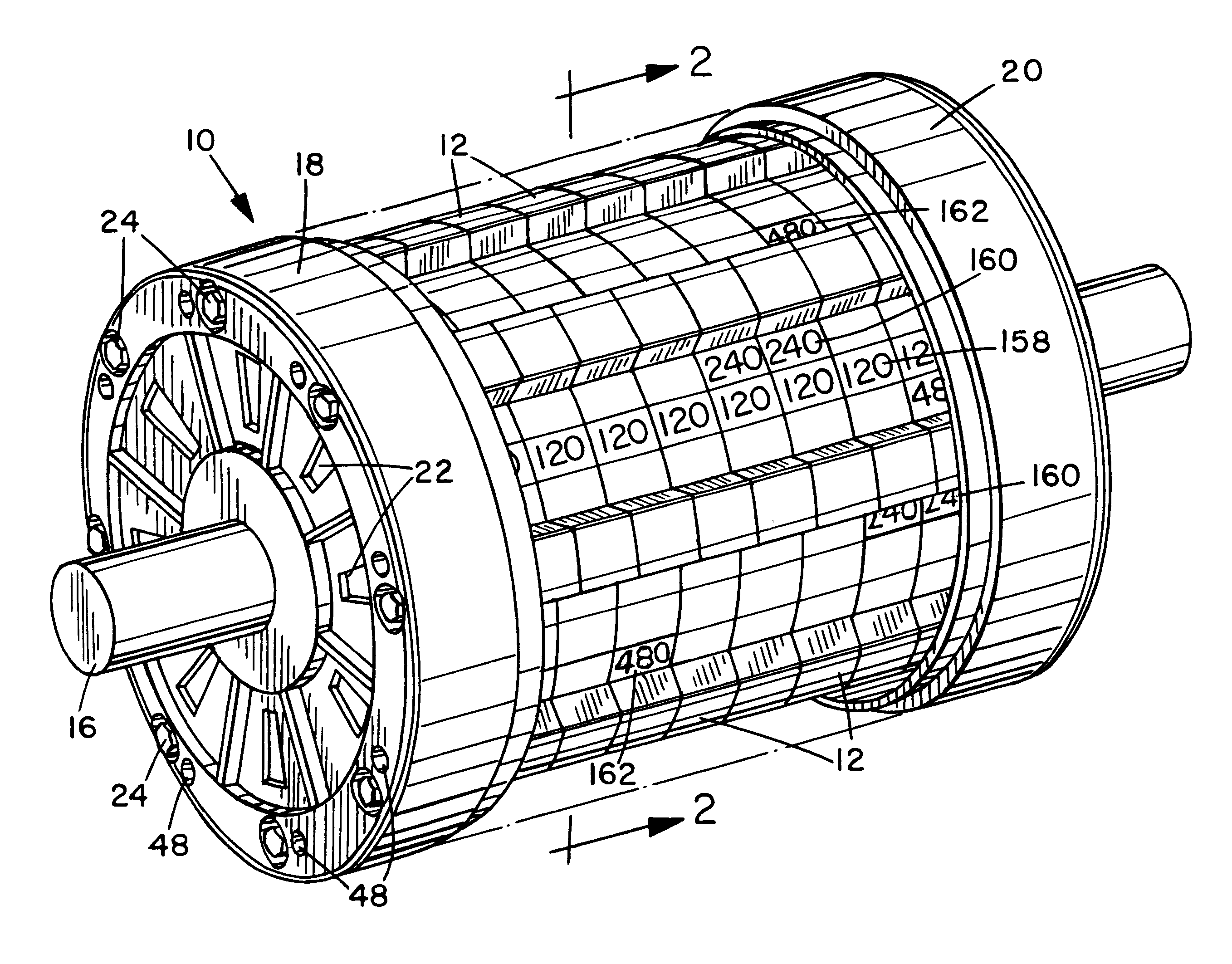
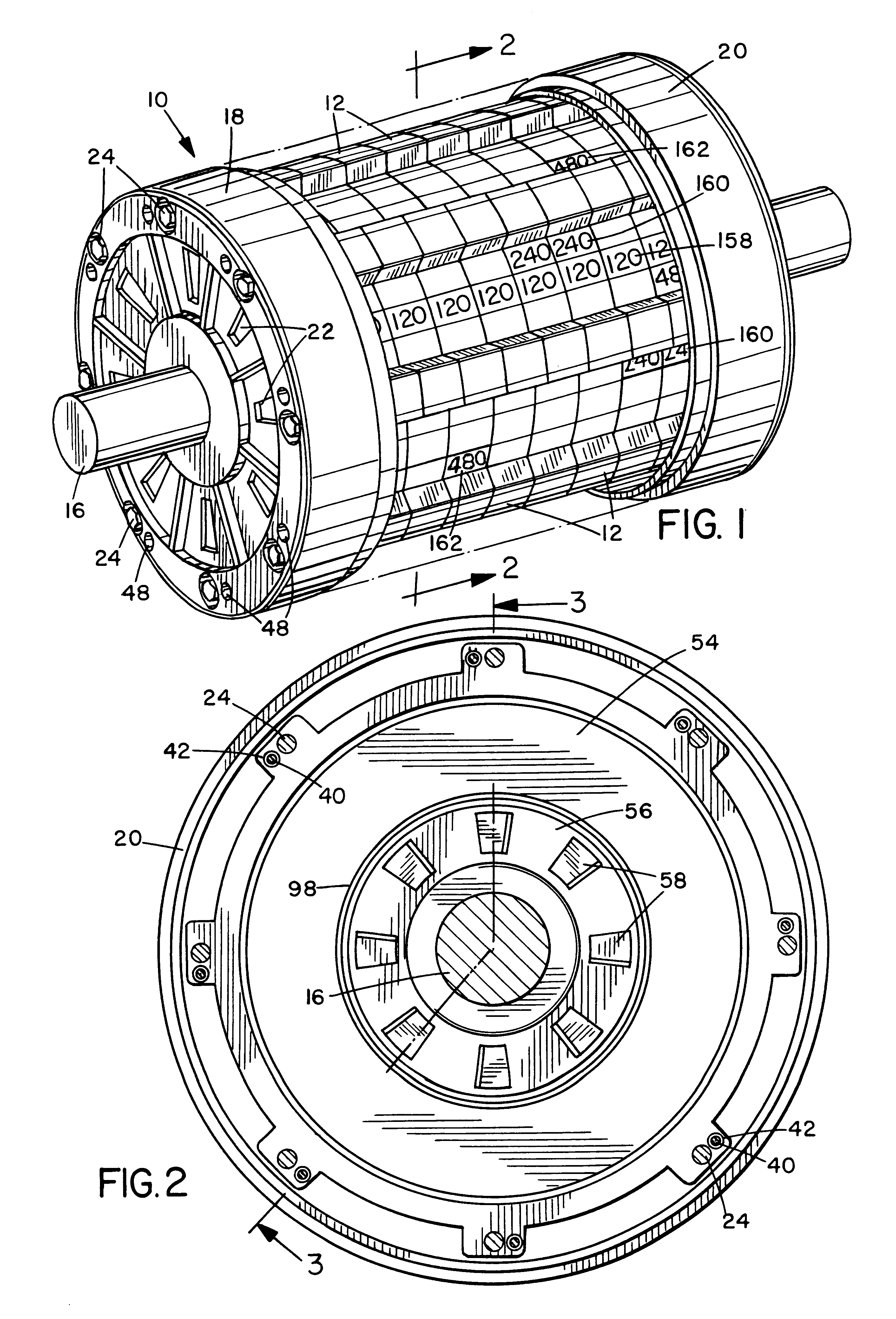
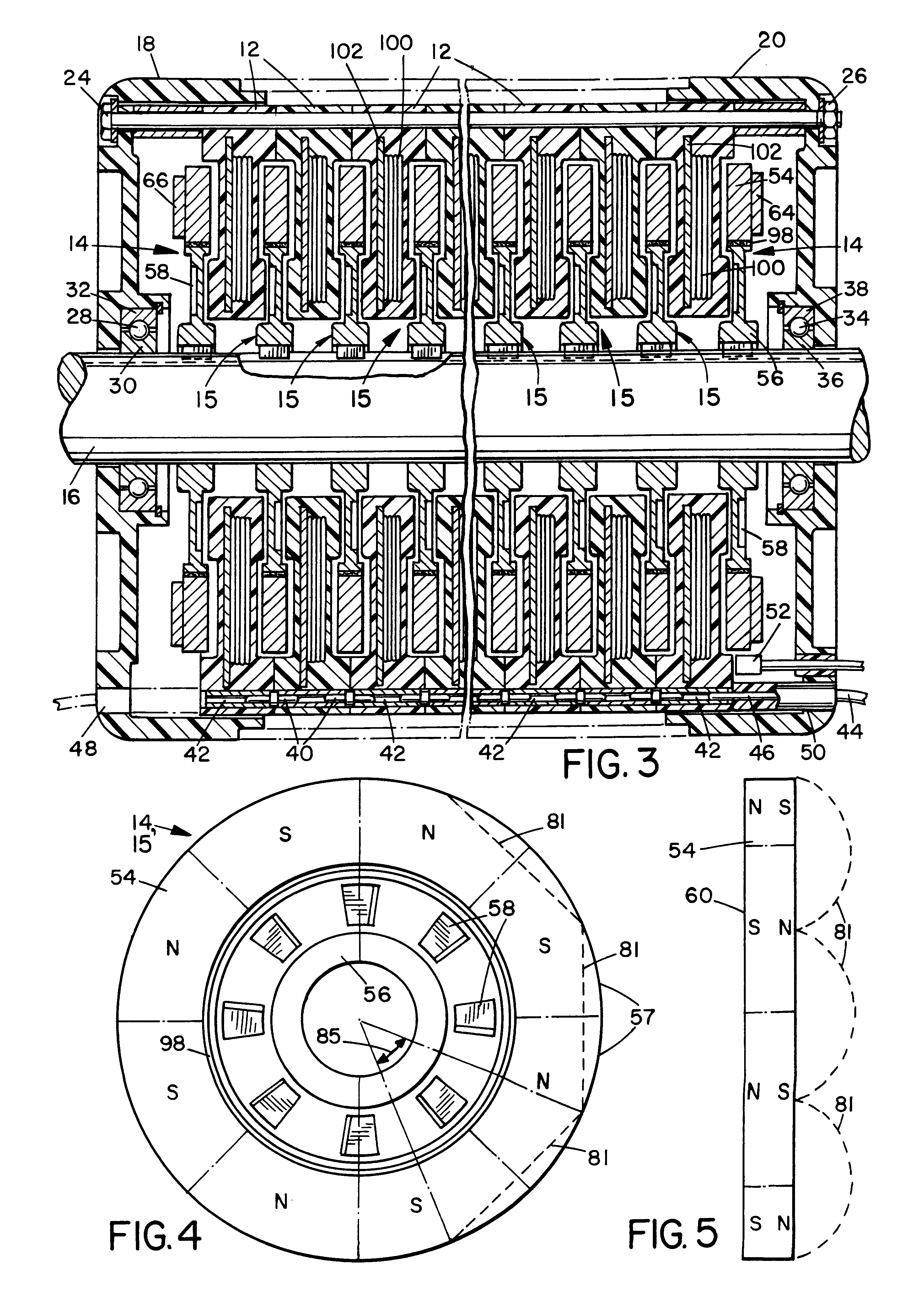
As illustrated in FIGS. 1-3, a motor / generator includes a housing 10 (the center section of which is shown removed), multiple layers or stator assemblies 12 connected to one another and disposed within housing 10, and a rotor having multiple rotor discs 14 connected to a shaft 16 that extends axially through housing 10. Housing 10 includes two endpieces 18 and 20, each having multiple housing ventilation openings 22. Housing 10 also includes at least one removable midsection piece between endpieces 18 and 20 that is indicated in phantom line in FIGS. 1-3 but not shown for purposes of clarity. Endpieces 18 and 20 and the removable midsection pieces are preferably made of light-weight plastic. Bolts 24 extend from endpiece 18 axially through housing 10 through each stator assembly 12 and are secured by nuts 26 at endpiece 20. At one end of housing 20, ball bearings 28 retained between a first bearing race 30 connected to shaft 16 and a second bearing race 32 connected to endpiece 18 f...


PUM


Abstract

An axial field motor / generator having a rotor that includes at least three annular discs magnetized to provide multiple sector-shaped poles. Each sector has a polarity opposite that of an adjacent sector, and each sector is polarized through the thickness of the disc. The poles of each magnet are aligned with opposite poles of each adjacent magnet. Metal members adjacent the outermost two magnets contain the flux. The motor / generator also has a stator that includes a stator assembly between each two adjacent magnets. Each stator assembly includes one or more conductors or windings. Although the conductors may be formed of wire having a round, uniform cross-section, they may alternatively be formed of conductors having a tapered cross-section that corresponds to the taper of the sectors in order to maximize the density of the conductor in the gap between axially adjacent poles. The conductors may also alternatively be formed of traces in a printed circuit, which may have one or more layers. Each stator assembly may be removably connectable to another stator assembly to provide modularity in manufacturing and to facilitate selection of the voltage at which the motor / generator is to operate. Electrical contacts, such as pins extending from the casing, may removably connect the conductors of adjacent stator assemblies. A magnet may be dynamically balanced on the shaft by hardening a thin ring-of cross-linked resin between the magnet and the shaft while the shaft is spun, using ultraviolet light to polymerize the resin.

Description

1. Field of the InventionThe present invention relates generally to electric motor / generators and, more specifically, to a permanent magnet, axial field motor / generator.2. Description of the Related ArtAn electric motor, which is a machine for converting current into motion, typically includes a rotor that rotates within a stator in response to a magnetic field. In a permanent magnet motor, the rotor or stator, typically the stator, includes one or more permanent magnets that generate a magnetic field. Permanent magnets may be made of ferrous metals or ferroceramic materials. Because the machine may also be used to convert motion into electric current, the machine is often referred to in the art as a motor / generator or a dynamo. Therefore, although the term "motor" is used herein for convenience, it should be understood that the same machine may be used as a generator.The rotor or stator of a permanent magnet motor, typically the rotor, includes conductors, such as copper wire, woun...

Claims


Application Information

Patent Timeline
Patent Type & Authority Patents(United States)
IPC IPC(8): H02K3/28H02K3/26H02K3/46H02K3/47H02K3/04H02K21/12H02K15/03H02K15/16H02K15/00H02K21/24H02K29/06H02K1/00H02K1/02H02K29/08H02K1/27H02K16/00H02K29/00H02K3/34
CPCH02K3/04H02K3/26H02K3/28H02K3/47H02K15/03H02K15/165H02K21/24B60L1/02B60L3/0061B60L15/20H02K1/02Y02T10/641H02K16/00H02K29/08H02K2203/03H02K2203/09B60L2200/36B60L2220/16B60L2220/44B60L2240/36B60L2240/421B60L2240/423B60L2270/145Y02T10/7275Y02T10/642H02K1/27Y02T10/72Y02T10/64
Inventor SMITH, STEPHEN H.SHENKAL, YUVAL
Owner SMITH TECH DEV LLC
Why Eureka
Try Eureka