Scanning confocal microscope with objective lens position tracking

a confocal microscope and objective lens technology, applied in the field of confocal microscopes, can solve the problems of not being stable in its realistic accuracy, affecting the operation of the microscope, and being relatively expensive and significant in its utility, and achieving the effect of improving the accuracy of the microscop

a confocal microscope and objective lens technology, applied in the field of confocal microscopes, can solve the problems of not being stable in its realistic accuracy, affecting the operation of the microscope, and being relatively expensive and significant in its utility, and achieving the effect of improving the accuracy of the microscop

US6181474B1Inactive Publication Date: 2001-01-30KOVEX CORP

Image

  • Scanning confocal microscope with objective lens position tracking
  • Scanning confocal microscope with objective lens position tracking
  • Scanning confocal microscope with objective lens position tracking

Examples


Embodiment Construction

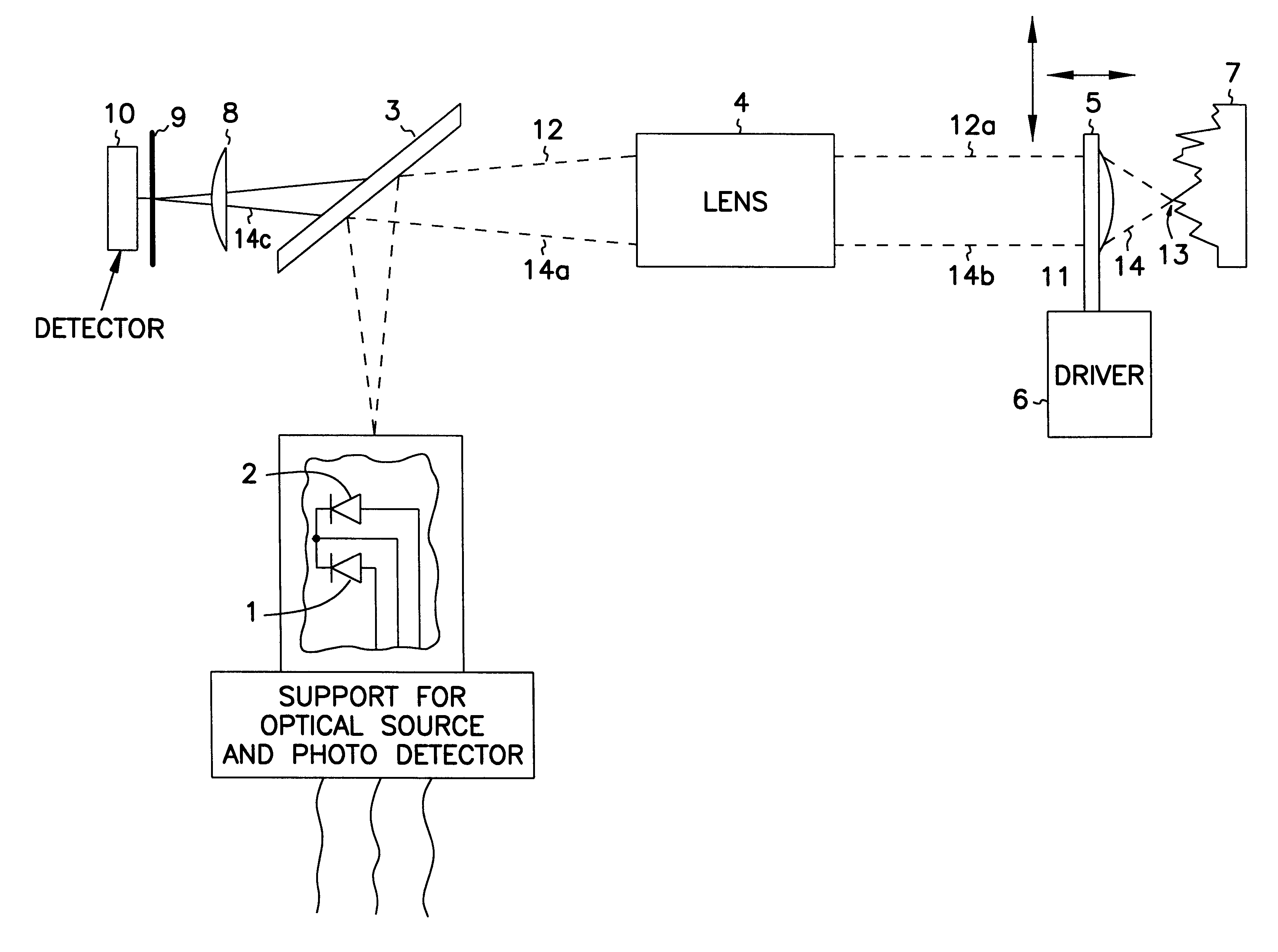
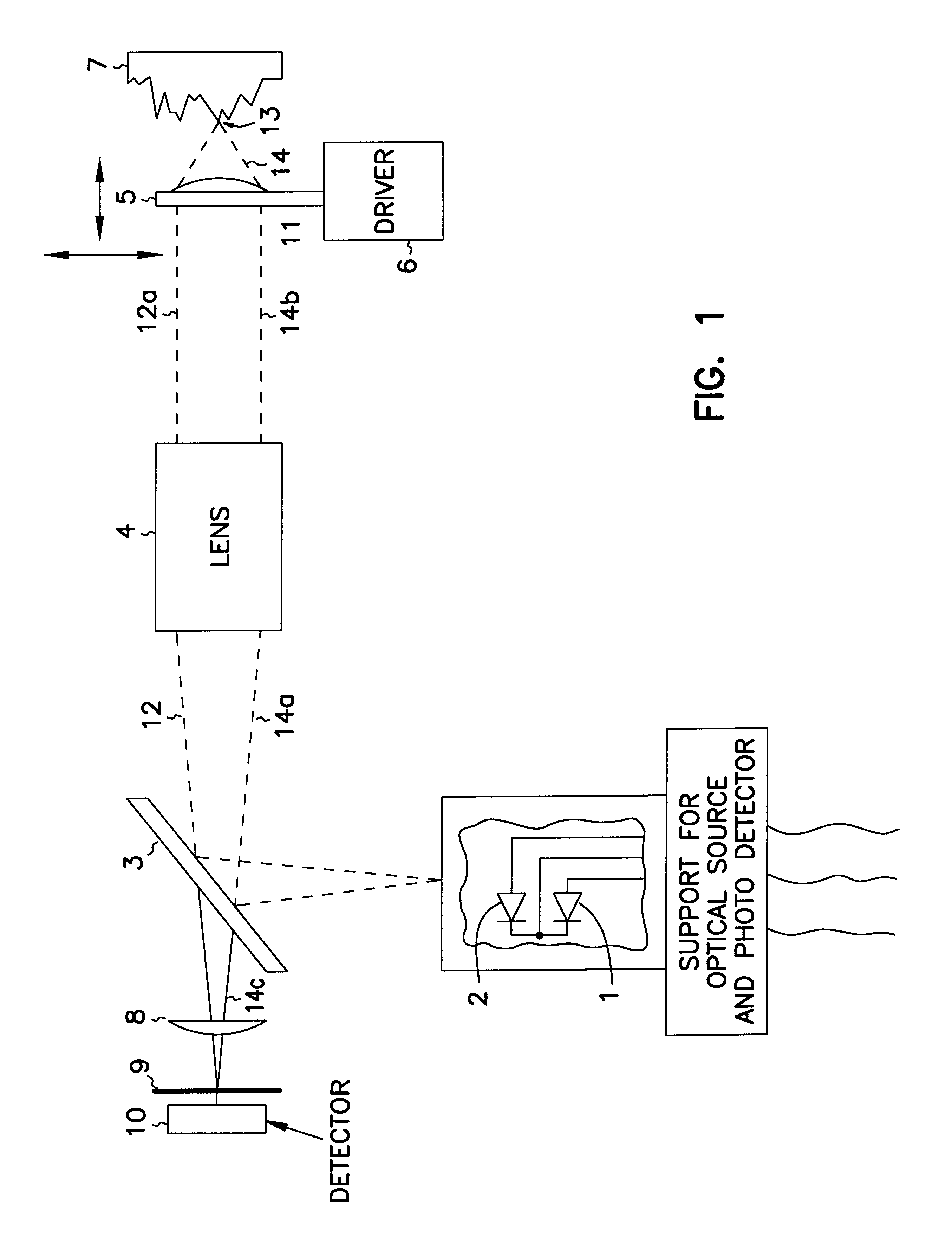
This example was used to determine the usefulness and accuracy of having a reference signal generated by a relatively thin, (compared to the focus scan amplitude) transparent object, i.e. cover glass window, transparent polymer film, and the like, placed between the sample being scanned and the moving objective. An in-focus signal that corresponds to a reference signal will be generated when the focal point of the laser beam is on either surface of the reference object. Hence, up to two reference signals will be detected before the data signals and then up to two reference signals will be detected after the data signals.

A Sony model KSS-240a CD player optical head (having a quadrilateral detection unit) obtained from a Sony model CDP-311 compact disk player was modified such that motions of the objective lens in the axis of the laser beam, i.e. the focus axis, were driven by a 2 Hz triangle waveform. The amplitude of the waveform caused the objectives amplitude of motion to be 2 mil...


PUM


Abstract

A calibration device which has at least two targets. Each target has at least one surface exhibiting areas of optical contrast, and each surface has a general plane of orientation. The targets are oriented such that a general plane of orientation of one target is inclined at an angle relative to the general plane of orientation of a surface of the second target which has areas of optical contrast.

Description

BACKGROUND OF THE ART1. Field of the InventionThis invention relates to confocal microscopes which detect light reflected or emitted from a sample. This invention also relates to scanning confocal microscopes which provide high quality images at relatively low cost, and which can scan samples in at least one axis using a moving objective lens. This invention also relates to confocal microscopy for the examination or inspection of surfaces with features that are desired to be within a predetermined height range. These type of surfaces include but are not limited to solder paste, ball grid arrays, and flip chip pads. Confocal microscopy eliminates light reflected or emitted from a sample from all but a thin depth of focus around the microscope focal point. This allows the confocal microscope to accurately determine the height of a given feature on a surface. This invention also relates to calibration of 3D optical metrology devices, including confocal microscopes.2. Background of the ...

Claims


Application Information

Patent Timeline
30 Jan 2001
Publication
US6181474B1
IPC
G02B21/00
CPC
G02B21/0052; G02B21/0056; G02B21/0084
Inventors
OUDERKIRK, STEVEN J.; BLAIR, ALAN