
Flip angle modulated magnetic resonance angiography

a magnetic resonance and flip angle technology, applied in the field of magnetic resonance angiography, can solve the problems of less specificity, hampered more widespread application of tof or pc mra techniques, and patients exposed to potentially harmful ionizing radiation, so as to improve signal enhancement, enhance the acquired nmr signal, and improve the effect of signal enhancemen

Inactive Publication Date: 2001-03-06
MAYO FOUND FOR MEDICAL EDUCATION & RES
View PDF5 Cites 23 Cited by
  • Summary
  • Abstract
  • Description
  • Claims
  • Application Information

AI Technical Summary

Benefits of technology

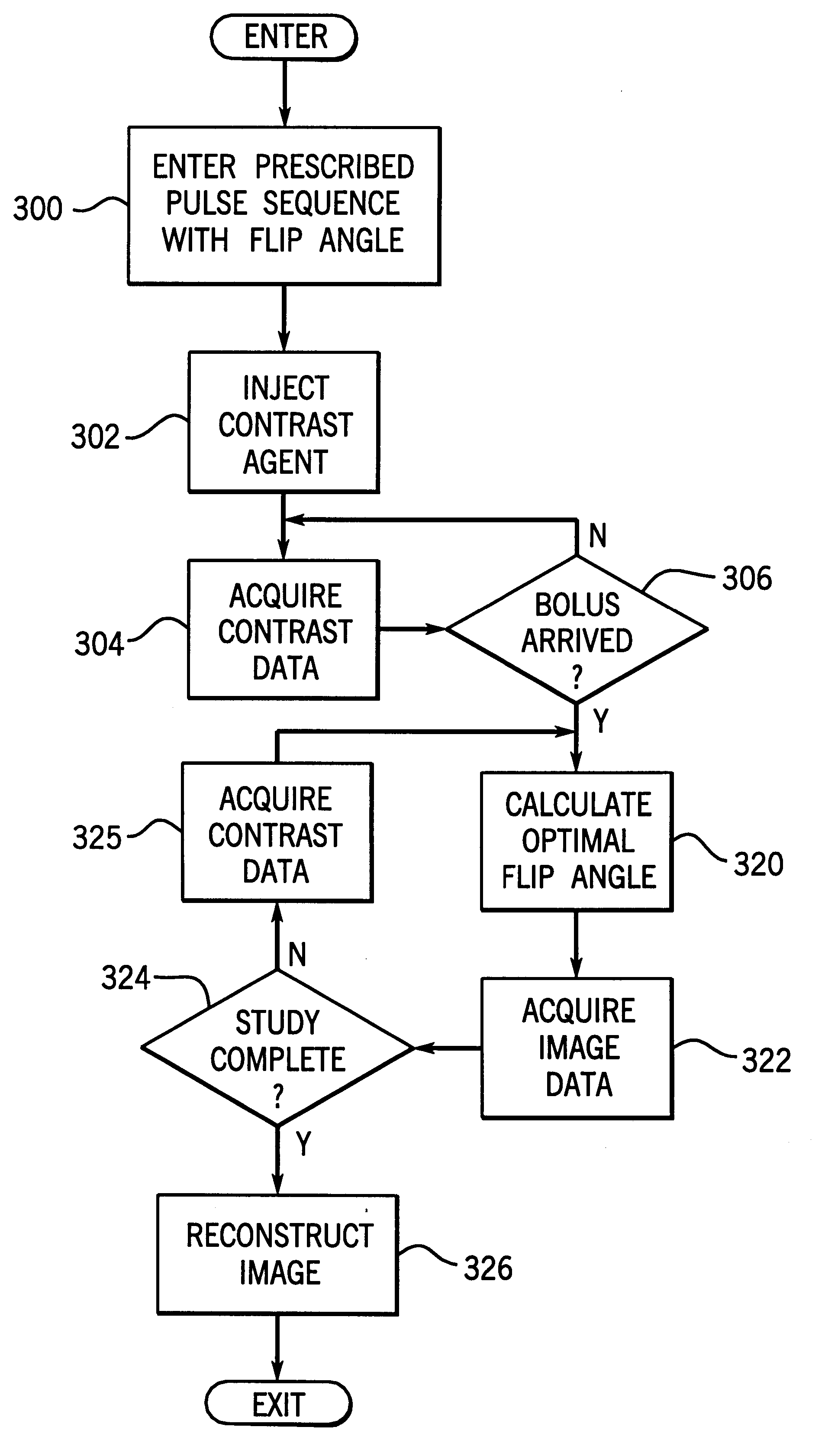
With either technique a significant improvement in signal enhancement is achieved by modulating the flip angle during the dynamic study. As shown in FIG. 6, the enhancement to the acquired NMR signals as a function of time when a fixed flip angle is used is shown by the solid line 14. When the present invention is used the signal enhancement is improved as indicated by dashed line 16. The improvement in the acquired NMR signal is particularly important late in the acquisition when the normalized concentration curve tapers off. Since the peripheral region of k-space is usually sampled during this later time, the signal quality is improved and detailed information is more accurately depicted in the reconstructed image.

Problems solved by technology

Unfortunately, however, these x-ray methods subject the patient to potentially harmful ionizing radiation and often require the use of an invasive catheter to inject a contrast agent into the vasculature to be imaged.
More widespread application of either TOF or PC MRA techniques is hampered by the presence of a variety of deleterious image artifacts, which can mask and, in some cases, even mimic pathology.
These artifacts generally result in a lower specificity, as well as compromised sensitivity.
This is not an easy timing to achieve as part of a routine clinical procedure because the delay time between intravenous injection to arrival in the arterial vasculature of interest is highly patient-dependent.

Method used


Image

  • Flip angle modulated magnetic resonance angiography
  • Flip angle modulated magnetic resonance angiography
  • Flip angle modulated magnetic resonance angiography

Examples


Embodiment Construction

Referring first to FIG. 1, there is shown the major components of a

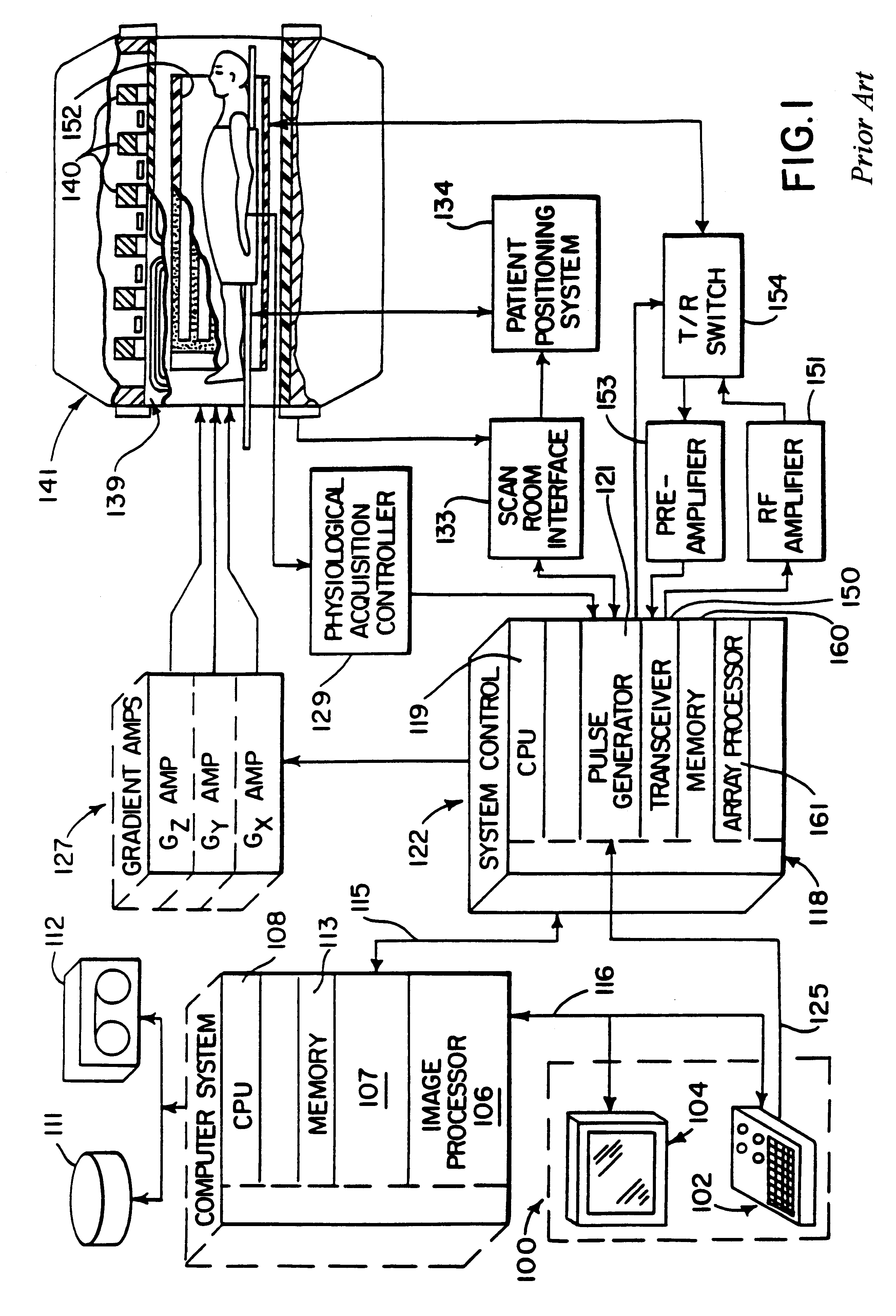
preferred MRI system which incorporates the present invention. The operation of the system is controlled from an operator console 100 which includes a keyboard and control panel 102 and a display 104. The console 100 communicates through a link 116 with a separate computer system 107 that enables an operator to control the production and display of images on the screen 104. The computer system 107 includes a number of modules which communicate with each other through a backplane 118. These include an image processor module 106, a CPU module 108 and a memory module 113, known in the art as a frame buffer for storing image data arrays. The computer system 107 is linked to a disk storage 111 and a tape drive 112 for storage of image data and programs, and it communicates with a separate system control 122 through a high speed serial link 115.

The system control 122 includes a set of modules connected together by a backpl...


PUM


Abstract

A dynamic MRA study of a subject is performed using a 3D fast gradient-recalled echo pulse sequence after the subject is injected with a contrast agent. The flip angle of an rf excitation pulse in the pulse sequence is modulated during the acquisition as a function of contrast agent concentration in the region of interest. In one embodiment the flip angle is updated by interleaving measurement pulse sequences which measure in real-time contrast agent concentration. In another embodiment the contrast concentration profile is determined in advance and a corresponding table of optimal flip angles are calculated and played out during the image acquisition.

Description

The field of the invention is magnetic resonance angiography ("MRA"), and particularly, dynamic studies of the human vasculature using contrast agents which enhance the NMR signals.Diagnostic studies of the human vasculature have many medical applications. X-ray imaging methods such as digital subtraction angiography ("DSA") have found wide use in the visualization of the cardiovascular system, including the heart and associated blood vessels. Images showing the circulation of blood in the arteries and veins of the kidneys and the carotid arteries and veins of the neck and head have immense diagnostic utility. Unfortunately, however, these x-ray methods subject the patient to potentially harmful ionizing radiation and often require the use of an invasive catheter to inject a contrast agent into the vasculature to be imaged.Magnetic resonance angiography (MRA) uses the nuclear magnetic resonance (NMR) phenomenon to produce images of the human vasculature. When a substance such as hum...

Claims


Application Information

Patent Timeline
IPC IPC(8): G01R33/563G01R33/54G01R33/561
CPCG01R33/563G01R33/5613G01R33/5616
Inventor FAIN, SEAN B.RIEDERER, STEPHEN J.
Owner MAYO FOUND FOR MEDICAL EDUCATION & RES
Learn More