Surface acoustic wave transponder configuration

a transponder and surface acoustic wave technology, applied in the direction of generators/motors, instruments, using reradiation, etc., can solve the problems of short transmission time between the radio frequency interrogation system and the transponder, the trade-off between the substrate size and the available encoding complexity, and the substrate siz

Inactive Publication Date: 2001-03-27
X CYTE
View PDF151 Cites 40 Cited by
  • Summary
  • Abstract
  • Description
  • Claims
  • Application Information

AI Technical Summary

Benefits of technology

One aspect of the present invention provides an acoustic beam path on the substrate having at least one reflection or acoustic beam redirection at an angle differing from .pi. / 2 radians. This redirection may be by acoustic reflection, trackchangers (electroacoustic devices which efficiently receive and transmit acoustic waves having differing propagation vectors, typically inclined at .pi. / 4 radians), acoustic waveguide structures, or the like. As such, the acoustic path is bent, thereby reducing the linear dimension of the substrate required for a given maximum acoustic path length. Partially reflective elements may also be used to split acoustic beam energy, providing multiple acoustic paths.
It is a still further object of an embodiment according to the present invention to provide an acoustic wave identification transponder having an angled elongated conductor having means for reflecting the acoustic wave to follow a path defined between portions of the angled elongated conductor. In this way, an electroacoustic transducer may be formed between adjacent portions of the path. Further, multiple electroacoustic transducers may be disposed in a common portion of the acoustic path.

Problems solved by technology

These time delays therefore dictate the minimum path length, and therefore size of the substrate.
Therefore, a tradeoff exists between substrate size and available encoding complexity.
Thus, the time for transmission between the radio frequency interrogation system and the transponder is typically short as compared to the acoustic delay of the substrate.
However, efficiency is lost with increasing acoustic path complexity (i.e., power splitting), and a large number of distinct acoustic waves reduces the signal strength of the signal encoding the information in each.
Therefore, the transponder design is a tradeoff between device codespace complexity and efficiency.
These systems require broadband transponder signal analysis, and thus cannot typically employ audio frequency (low frequency) analysis systems.
As the number of sets of delay pads increases, the signal to noise ratio in the transponder reply signal is severely degraded.
This limitation on the number of tap transducers places a limitation on the length of the informational code imparted in the transponder replies.
This is because the tap transducers additionally act as launch transducers as well as partial reflectors of the surface acoustic wave so that an increase in the number of tap transducers results in a corresponding increase in spurious signals in the transponder replies.
This limitation on the number of tap transducers places a limitation on the length of the informational code imparted in the transponder replies.

Method used


Image

  • Surface acoustic wave transponder configuration
  • Surface acoustic wave transponder configuration
  • Surface acoustic wave transponder configuration

Examples


example 2

FIGS. 10A and 10B show constellation patterns of quadrature amplitude modulation patterns (QAM), in this case QAM-16 and QAM-18 polar modulation. These patterns demonstrate the separation of modulation states by varying phase and amplitude of a signal. Various QAM constellation exist, including rectangular, polar, elliptic, irregular, and those with incomplete code sets. For example, in the QAM-18 scheme, the 0-phase, 0-amplitude code is unused according to the present invention.

example 3

FIGS. 11A-11C show a beam coverage pattern for a patch-like antenna, polarization axes and potential for spatial discrimination of a tag. By providing lobular and polarized radio frequency transmission patterns, tags in proximity to an interrogation system may be distinguished. For example, where two tags have slightly differing orientations within the interrogation field, a null steered polarization technique may be used. In this case, one transponder produces a substantial output while another transponder is at a "null" or relatively low output level. This may be achieved by differential phase delays, group delays, or frequency responses, for example. Active phased array antennas may also be employed. As an example of this is, a unique set of three different delays associated with any one tag may be provided. Similar diversity may also be proposed in the frequency domain.

The polarization null steering relies on the assumption that each tag has been randomly placed on the article t...

example 4

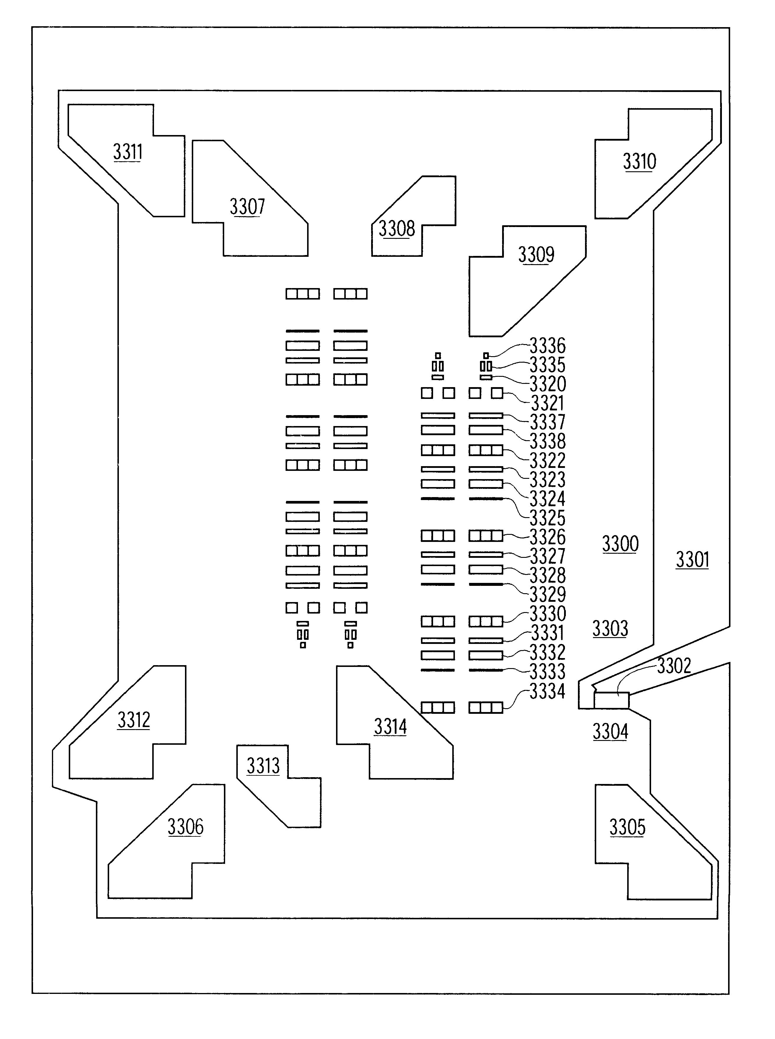
FIGS. 15-18 show differing embodiments of the acoustic transponder tag according to the present invention. The thick dark line 702 represents the buss bar that drives the transducers 703, 704, 705, 706, 707, 708, 709. The bus bar 702 is laid out in the manner shown so as to enable the RF energy to be inductively coupled into the buss bar 702. As the buss bar 702 passes around the square substrate 700, having a side length of about 10 mm, for the second time it provides the means of driving the transducer 703, 704, 705, 706, 707, 708, 709 located at that respective location with the appropriate differential signal. Each transducer 703, 704, 705, 706, 707, 708, 709 so placed will split the available RF power equally in accord with the number of transducers. This same power loss will be sustained again on the reflected path, i.e. the overall loss due to the split will be 20 log(N). Table 2 provides, in more detail, an analysis of the signal strength of the received signal. Hence the nu...


PUM


Abstract

An acoustic wave identification transponder device, having a substrate, an electroacoustic transducer generating an acoustic wave in said substrate and a set of encoding elements disposed in a path of the acoustic wave for modifying the acoustic wave, having elements which reflect portions of the acoustic wave having a component orthogonal to the incident wave. The reflectors may be, for example, trackchangers or reflective arrays compressors (RAC). The wave may be phase-amplitude modulated for increased efficiency expressed in bits per tap. Such phase amplitude modulation is preferably imposed by partial beam width phase delay elements disposed within an acoustic beam path.

Description

The present invention relates to new configuration of a surface acoustic wave transponder, and more particularly to a method and apparatus of improving the spatial and layout efficiency of surface acoustic wave encoded transponder having a folded acoustic path reducing a size of the otherwise required substrate.A known radio frequency passive acoustic transponder system produces individualized responses to an interrogation signal. The code space for these devices may be, for example, 2.sup.16 codes, or more, allowing a large number of transponders to be produced without code reuse. These devices provide a piezoelectric substrate on which an aluminum pattern is formed, for example by a typical microphotolithography process, with a minimum feature size of, for example, one micron.These codes are imposed upon a received signal by signal transforming elements formed on the substrate. Typically, for each encoded symbol, a separate transforming element is formed. In order to facilitate de...

Claims


Application Information

Patent Timeline
Patent Type & Authority Patents(United States)
IPC IPC(8): G06K19/067G06K7/00G01S13/34G01S13/75H03H9/64
CPCG01S13/755G06K7/0008G06K19/0672G06K19/0675H03H9/02795H03H9/44H03H9/6406G01S13/343
Inventor NYSEN, PAUL A.SKEIE, HALVOR
Owner X CYTE
Why Eureka
Try Eureka