Foam transport process for in-situ remediation of contaminated soils

a technology of in-situ remediation and foam transport, which is applied in the direction of other chemical processes, mixing, borehole/well accessories, etc., can solve the problems of poor penetration of water carrier stream into clay lenses and non-aqueous phase liquids, move in a downward direction, and contamination of soil, etc., to achieve the effect of cost-prohibitive excavating, difficult to treat without considerable risk, and poor penetration of water carrier stream

Inactive Publication Date: 2001-04-03
GAS TECH INST
View PDF27 Cites 124 Cited by
  • Summary
  • Abstract
  • Description
  • Claims
  • Application Information

AI Technical Summary

Problems solved by technology

The main disadvantage of this technique is that the water carrier stream provides poor penetration into clay lenses and non-aqueous phase liquids and moves in a downward direction, due to gravity, into the underlying groundwater.
Subsurface contamination of soil is typically caused by spills or waste impoundments that have leaked over many years and have been observed at a variety of industry and government-owned facilities.
Cleanup of contamination in the deep subsurface, that is 4 or more feet below the surface of the soil, is cost-prohibitive to excavate and difficult to treat without considerable risk to the groundwater.
The challenge is in developing a method of delivering the chemical and biological enhancements for in-situ remediation of the subsurface without inadvertently contaminating the underlying groundwater or uncontaminated soils surrounding the contaminated site.
All of these conventional methods for delivery of enhancement chemicals to the subsurface pose a considerable risk to groundwater because they involve the gravity flow of hundreds of thousands of gallons of chemical-bearing water streams that can move through contaminated regions of the subsurface, pick up considerable concentrations of pollutants and flow past non-aqueous phase liquids and clay lenses into the underlying and surrounding groundwater aquifers.
The primary problem with water-based delivery systems for chemicals transport in the subsurface is that gravitational forces have a dominating influence over the direction of flow of these fluids, thereby resulting in increased risk to groundwater.
The liberated gas creates a gas lift to discharge a fracturing fluid from the formation and return the fracturing fluid to the surface, resulting not only in fracturing, but also cleanout of the formation.
Because high pressures tend to stabilize these foams, their use in shallow formations, where pollutants are located at contaminated sites, usually less than several hundred feet below the surface, results in a failure to maintain stable bubble formation.
In addition, oil-production foam formulations are tailored in rheological properties to achieve specific tasks related to petroleum recovery or gas storage and, thus, are inappropriate for site remediation applications.
In foam remediation, by contrast, partial removal of contaminants is unsatisfactory, the objective being to achieve efficient removal of pollutants from soil particles and non-aqueous phase liquids in the subsurface regions.
Ionic surfactants such as those commonly employed in enhanced oil or gas recovery systems, sorb to the soil material, thereby becoming lost from the solution.
The inability to collapse the foam into a fluid, such as would be the case with foams utilized in enhanced oil or gas recovery systems, which foams are highly stable, complicates this separation.
In addition, highly stable foams may limit or inhibit the biodegradation of solubilized contaminants and the surfactant material remaining in the soil.

Method used


Image

  • Foam transport process for in-situ remediation of contaminated soils
  • Foam transport process for in-situ remediation of contaminated soils

Examples


Embodiment Construction

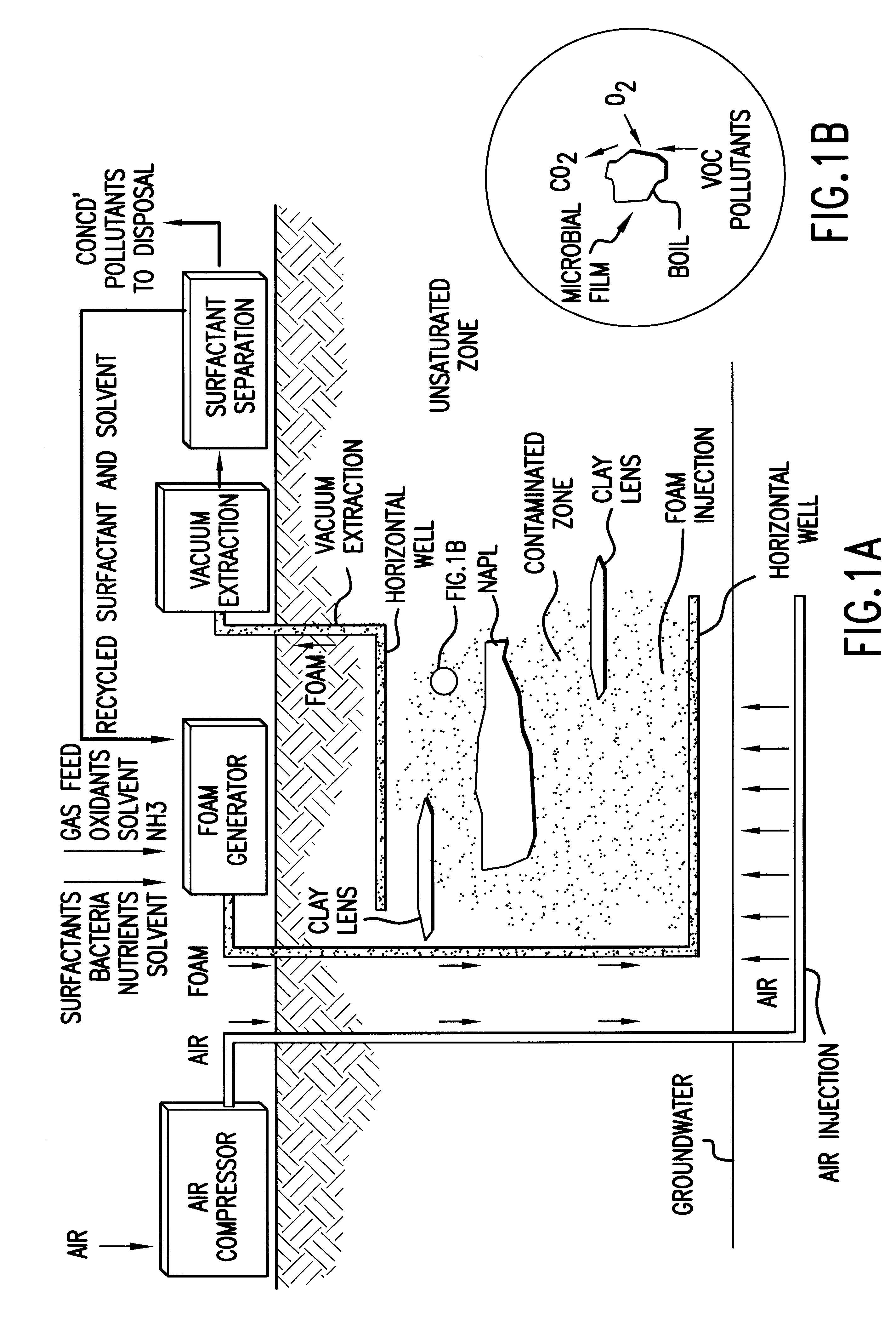
FIG. 1 shows a schematic diagram of the process for in-situ remediation of contaminated soils in accordance with one embodiment of this invention in which foam is introduced into the underground in-situ contaminated treatment zone through horizontal wells. In particular, the foam having the requisite characteristics for use in accordance with the process of this invention is produced in a foam generator by passing a gas through a finely divided frit submerged in an aqueous solution containing a surfactant and the desired treatment agents, that is, nutrients, trace metals, bacteria, oxidants, solvents, and the like. The surfactant is preferably a non-ionic surfactant which produces a foam which is collapsible in the underground in-situ treatment zone. The gas used for making the foam may also contain nutrients, for example ammonia, nitrous oxide, triethyl phosphate, and the like, or solvents, such as methanol and / or ethanol.

The foam, which is produced under pressure, that is greater ...


PUM

PropertyMeasurementUnit
diameteraaaaaaaaaa
pressureaaaaaaaaaa
sizesaaaaaaaaaa

Abstract

A process for in-situ remediation of contaminated soil in which at least one treating agent is introduced into the contaminated soil and transported to an underground in-situ treatment zone of the contaminated soil by a foam-based fluid.

Description

1. Field of the InventionThis invention relates to a process for in-situ remediation of contaminated soils by the addition of certain treatment agents, such as chemicals to enhance mass transfer of pollutants from soils and non-aqueous phase liquids and to stimulate bacteria to degrade organic pollutants. More particularly, this invention relates to an improved method for the delivery of chemicals for enhancing bioremediation and for the physico-chemical separation and removal of pollutants from contaminated soil and groundwater whereby the pollutants are desorbed from the soil and non-aqueous phase liquids, such as tar and oil, and are available for biodegradation and / or physical removal from the soil by a mobile foam fluid phase. This invention also relates to a method for enhancing electrokinetic, electromagnetic and radio frequency (RF) in-situ treatment processes for in-situ treatment of inorganic and hydrocarbon pollutants in contaminated soils using foams.2. Description of Pr...

Claims


Application Information

Patent Timeline
Patent Type & Authority Patents(United States)
IPC IPC(8): B09C1/10B09C1/00E21B43/40E21B43/25E21B43/34
CPCB09C1/00B09C1/10E21B43/25E21B43/40B09C2101/00
Inventor HAYES, THOMAS D.
Owner GAS TECH INST
Why Eureka
Try Eureka