Direct hydrocarbon fuel cells

Inactive Publication Date: 2001-04-10
NORTHWESTERN UNIV
View PDF2 Cites 83 Cited by
  • Summary
  • Abstract
  • Description
  • Claims
  • Application Information

AI Technical Summary

Benefits of technology

FIG. 5 is a table showing conditions that limit and promote carbon deposition, as compared to various Ni-YDC anodes and the parenthetical reference to Ni weight percent therein. While such percentages are shown with respect to eth

Problems solved by technology

There are a considerable number of problems and the deficiencies a

Method used


Image

  • Direct hydrocarbon fuel cells
  • Direct hydrocarbon fuel cells
  • Direct hydrocarbon fuel cells

Examples


example 1

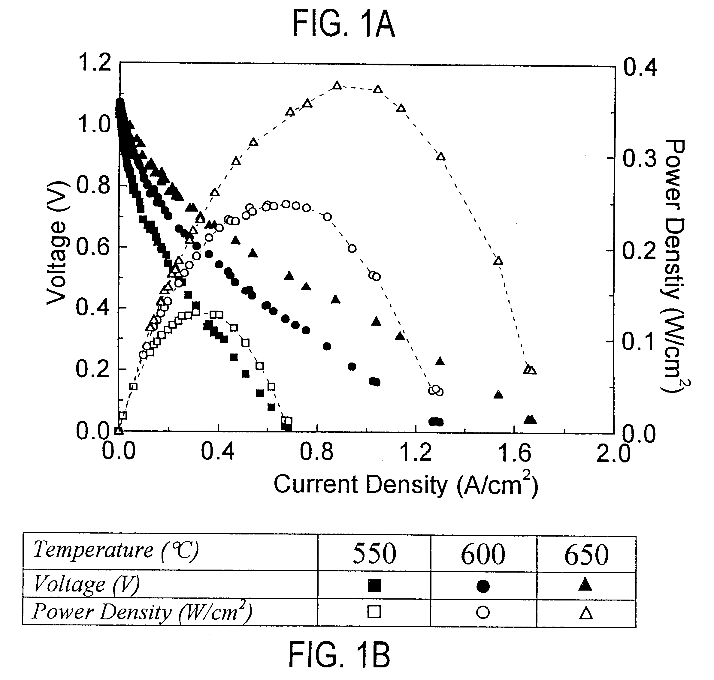
Single-cell current-voltage measurements were carried out in air and methane. Identical results were obtained for pure and humidified (containing 3% H.sub.2 O ) methane in the early stages of cell tests; while cell performance was stable with dry methane, after .apprxeq.2hrs of testing in humidified methane, cell performance degraded because of oxidation of the anode Ni. FIG. 1 shows the measured current density and power density vs. voltage. The open-circuit voltage (OCV) was 1.06V. The current density vs. voltage curves were non-ohmic indicating a substantial electrode overpotential. Based on prior studies of

these cells operated on hydrogen fuel, the current densities were limited primarily by cathode, overpotential. Current densities increased with increasing temperature, such that maximum power density increased from 250 mW / cm.sup.2 at 600.degree. C. to 370 mW / cm.sup.2 at 650.degree. C.

example 2

By way of comparison, the results of Example 1 were similar to those obtained for cells operated with humidified hydrogen fuel, except that the power densities were .apprxeq.20% greater. Visual observation, energy dispersive x-ray (EDX), and scanning electron microscopy (SEM) observations of the anodes, carried out after the call tests, showed no evidence of carbon deposition after .apprxeq.100 hrs of operation.

example 3

Successful cell operation on dry methane (Example 1) indicated that direct electrochemical oxidation,

CH.sub.4 +2O.sub.2 =2H.sub.2 O+CO.sub.2.DELTA.G.degree.(600.degree. C.)=-800 kJ / mol (3)

was the primary anode reaction mechanism. The OCV values measured in Example 1, .apprxeq.1.06V, were typically very close to the values measured for these cells operated with 97%H.sub.2 +3%H.sub.2 O fuel. This is reasonable given that the .DELTA.G.degree.(600.degree. C.) values are similar for eqn. 3 and hydrogen oxidation. The exact Nernst potential for eqn. 3 cannot be calculated since the, H.sub.2 O and CO.sub.2 partial pressures are not known, but the measured OCV.sub.s suggest reasonable values, <0.18 atm for H.sub.2 O and <0.09 atm. CO.sub.2.

While eqn. 3 shows electrochemical oxidation of methane, it should be noted that the present invention contemplates the possibility of other reaction mechanisms for the desired oxidation products. For instance, various intermediate reactions and / or specie...


PUM


Abstract

The direct electrochemical oxidation of hydrocarbons in solid oxide fuel cells, to generate greater power densities at lower temperatures without carbon deposition. The performance obtained is comparable to that of fuel cells used for hydrogen, and is achieved by using novel anode composites at low operating temperatures.

Description

This invention relates generally to direct use of hydrocarbons in fuel cells and, more particularly, methods, fuel cells and components thereof relating to such use.BACKGROUND OF INVENTIONFuel cells are promising electrical power generation technologies, with key advantages including high efficiency and low pollution. Most potential near-term applications of fuel cells require the use of hydrocarbon fuels such as methane, for which a supply infrastructure is currently available. However, fuel cells typically operate only with hydrogen as the fuel. Thus, current demonstration power plants and planned fuel-cell electric vehicles must include a hydrocarbon fuel reformer to convert the hydrocarbon fuel to hydrogen. Fuel cells that could operate directly on hydrocarbon fuels would eliminate the need for a fuel reformer, providing considerable system and economic advantages and presumably improving the viability of the technology.Prior art fuel cells utilizing hydrocarbon fuels directly h...

Claims


Application Information

Patent Timeline
IPC IPC(8): H01M8/12H01M8/06H01M2/18H01M4/86H01M4/88H01M4/90H01M4/92H01M4/96H01M8/00H01M8/04H01M8/10H01M8/18
CPCH01M4/8621H01M4/8882H01M4/90H01M8/0637H01M8/1253H01M8/126H01M4/9033H01M4/92Y02E60/521Y02E60/525Y02E60/50Y02P70/50
Inventor BARNETT, SCOTT A.MURRAY, ERICA PERRYTSAI, TSEPIN
Owner NORTHWESTERN UNIV
Why Eureka
Try Eureka