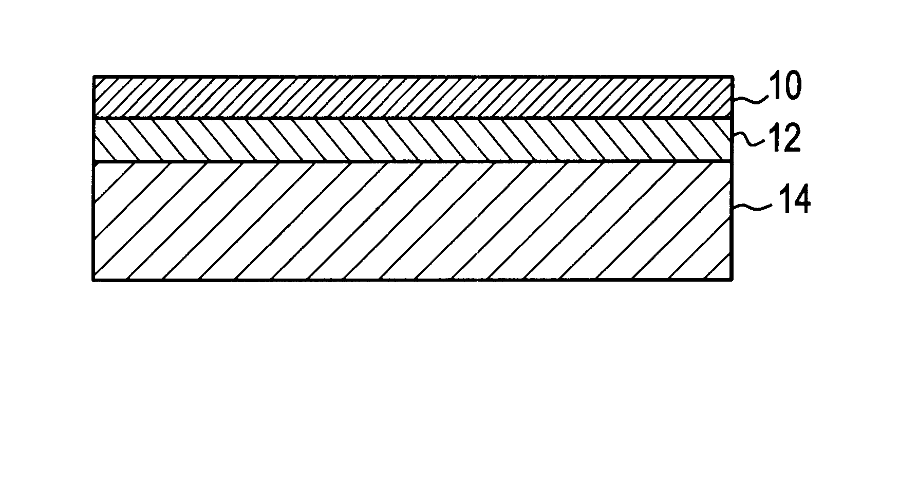
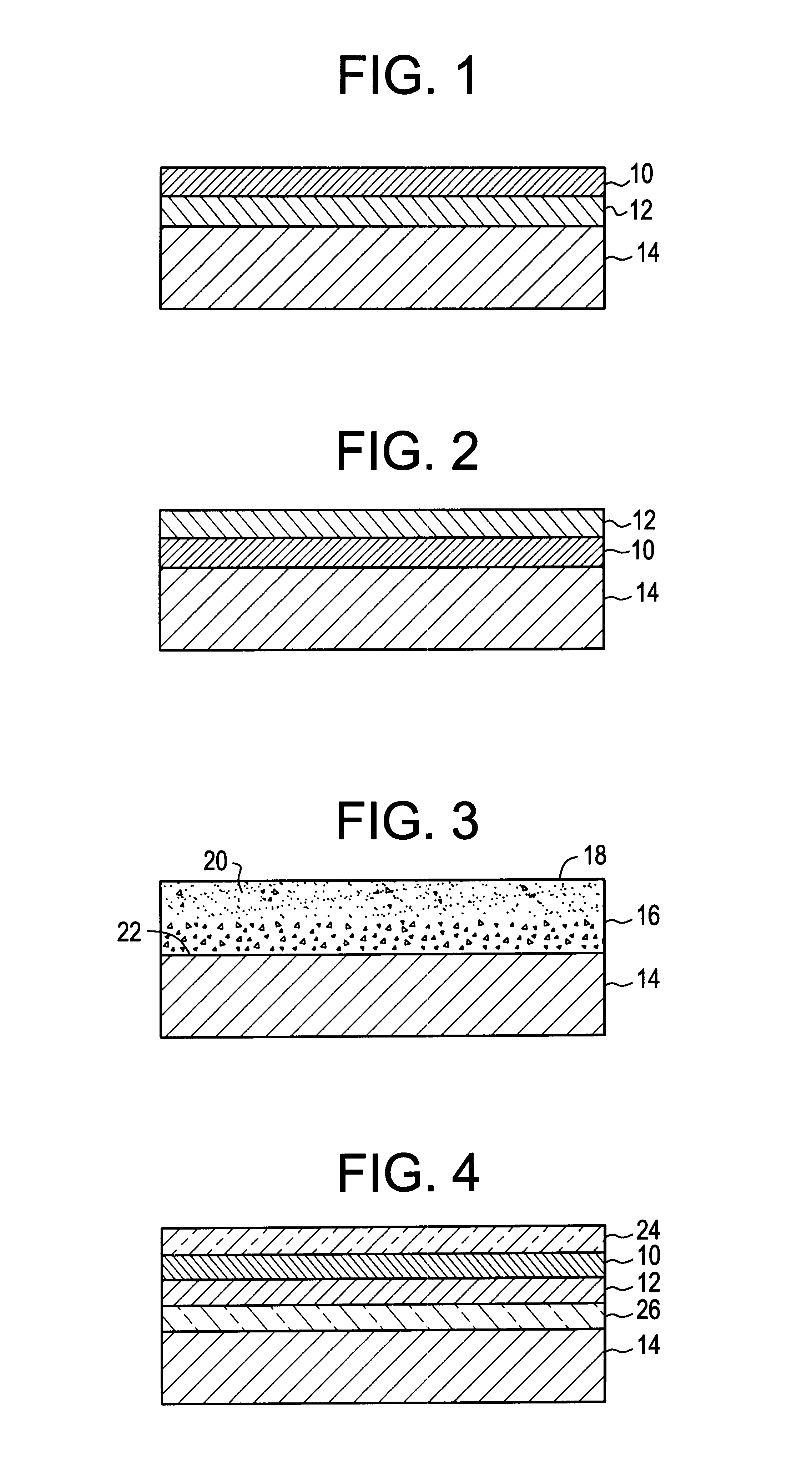
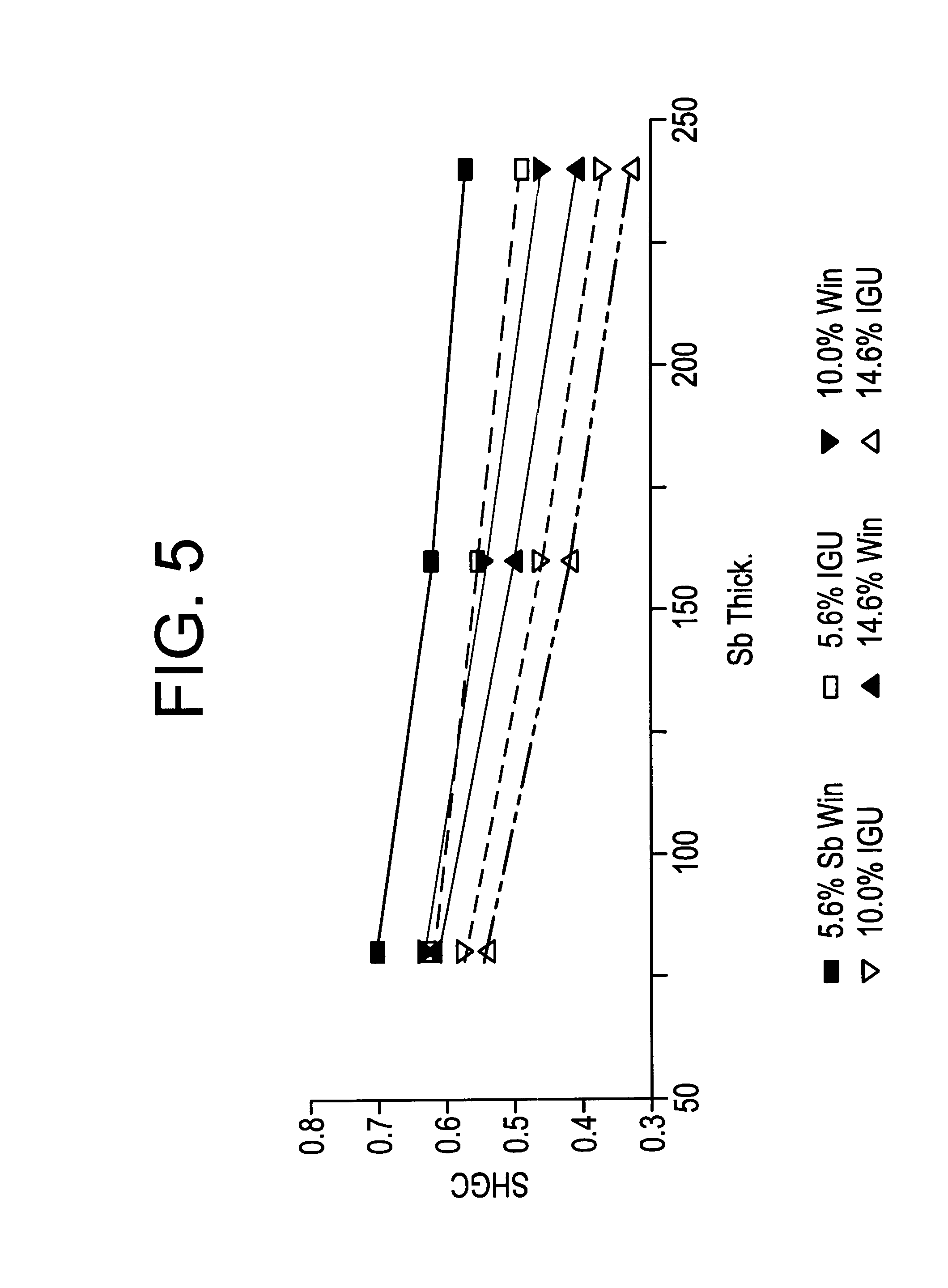
Solar control coated glass

a technology of solar control and coated glass, applied in the field of coated glass, can solve the problems of not teaching the process of coating glass articles, the patent does not teach how to produce coated glass articles, and no one system has successfully met all the performance requirements in an economic manner. , to achieve the effect of convenient application

Inactive Publication Date: 2001-04-17
ARKEMA INC
View PDF18 Cites 166 Cited by
  • Summary
  • Abstract
  • Description
  • Claims
  • Application Information

AI Technical Summary

Benefits of technology

An object of the invention is to prepare a transparent article with controlled reflected color (even neutral color as defined herein,) that will absorb solar near infrared (NIR) wavelength radiation and reflect mid-range infrared heat (low emissivity) comprising two thin film layers containing doped SnO.sub.2. Another object is the application of the layers by atmospheric pressure chemical vapor deposition (CVD) techniques, or by other processes such as solution spray or vaporized/sublimed liquids/solids can be utilized. The preferred method of application for this invention is atmospheric pressure CVD using vaporized liquid precursors. Another object is to provide multiple solar con

Problems solved by technology

As explained below, various technologies have been employed to meet the requirement for solar-control and low emissivity glass, however, no one system has successfully met all of the performance requirements in an economic manner.
In either case, these solar-control coatings do not contribute significant low emissivity properties to the glass article.
This patent does not teach how to produce coated glass articles which possess both solar-control and l

Method used


Image

  • Solar control coated glass
  • Solar control coated glass
  • Solar control coated glass

Examples


examples 1 to 30

A 2.2 mm thick glass substrate (soda lime silica), two inches square, was heated on a hot block to 605 to 625.degree. C. The substrate was positioned 25 mm under the center section of a vertical concentric tube coating nozzle. A carrier gas of dry air flowing at a rate of 15 liters per minute (l / min) was heated to 160.degree. C. and passed through a hot wall vertical vaporizer. A liquid coating solution containing .about.95 wt % monobutyltin trichloride and .about.5 wt % antimony trichloride was fed to the vaporizer via a syringe pump at a volume flow designed to give a 0.5 mol % organotin concentration in the gas composition. A quantity of water was also fed into the vaporizer at a flow designed to give a 1.5 mol % water vapor in the gas mixture. The gas mixture was allowed to impinge on the glass substrate at a face velocity of 0.9 m / sec for .about.6.1 seconds resulting in the deposition of a film of antimony doped tin oxide .about.240 nm thick. Immediately following, a second gas...

example 31 to 38

The procedure of Example 1 was repeated, except that the vapor feed order was reversed. The fluorine doped tin oxide film was deposited first for .about.8 seconds followed by the antimony doped tin oxide film for .about.6 seconds. The resulting film was .about.540 nm thick and composed of a low emissivity layer (TOF) of about 300 nm and a NIR layer (TOSb) of about 240 nm and had a similar appearance and reflected light color (Neutral-blue Color) as the film in example 19. The analysis results appear in Table 2, number 31. The procedure of this example was repeated 7 additional times with concentrations of chemical precursors and deposition times varied in order to produce coated glass samples having different thicknesses for the NIR and low emissivity layers and different dopant concentrations. The results are presented in Table 2

example 39

The procedure of Example 1 was repeated but utilizing three precursor feed mixtures. The composition of the third mixture was 90 wt % monobutyltin trichloride, 5 wt % trifluoroacetic acid, and 5 wt % antimony trichloride. A gradient film was deposited by first depositing only the antimony doped tin oxide precursor of Example 1 for 70% of the time needed to deposit 240 nm. Then the mixed antimony / fluorine doped precursor was started. Both precursor mixtures would continue for 20% of the total deposition time at which point the antimony precursor mixture was turned off. The antimony / fluorine mixed precursor was continued for the remaining 10% of the total deposition time for the 240 nm antimony film. At this point, the fluorine doped tin oxide film precursor feed was turned on. Both feeds were continued for 20% of the total time needed to deposit 300 nm of fluorine doped tin oxide. The mixed antimony / fluorine precursor feed was turned off and the fluorine doped tin precursor was conti...


PUM

PropertyMeasurementUnit
Fractionaaaaaaaaaa
Fractionaaaaaaaaaa
Fractionaaaaaaaaaa

Abstract

A solar-control glass that has acceptable visible light transmission, absorbs near infrared wavelength light (NIR) and reflects midrange infrared light (low emissivity mid IR) along with a preselected color within the visible light spectrum for reflected light is provided. Also provided is a method of producing the improved, coated, solar-controlled glass. The improved glass has a solar energy (NIR) absorbing layer comprising tin oxide having a dopant such as antimony and a low emissivity control layer (low emissivity) capable of reflecting midrange infrared light and comprising tin oxide having fluorine and/or phosphorus dopant. A separate iridescence color suppressing layer as described in the prior art is generally not needed to achieve a neutral (colorless) appearance for the coated glass, however an iridescence suppressing layer or other layers may be combined with the two layer assemblage provided by the present invention. If desired, multiple solar control and/or multiple low emissivity layers can be utilized. The NIR layer and the low emissivity layer can be separate portions of a single tin oxide film since both layers are composed of doped tin oxide. A method of producing the coated solar control glass is also provided.

Description

BACKGROUND OF INVENTIONThis invention relates to coated glass used in residential, architectural and vehicle windows and miscellaneous applications where both solar control and low emissivity properties are desired. The coatings for solar control and low emissivity contain tin oxide having various dopants. The invention avoids the need for an anti-iridescence underlayer. The glass articles may be of any shape but are typically flat or curved. The glass composition can very widely but is typically soda lime glass produced by the float process. It may be annealed, heat strengthened or tempered.DESCRIPTION OF PRIOR ARTSolar-control is a term describing the property of regulating the amount of solar heat energy which is allowed to pass through a glass article into an enclosed space such as a building or an automobile interior. Low emissivity is a term describing the property of an article's surface wherein the absorption and emission of mid-range infrared radiation is suppressed, making...

Claims


Application Information

Patent Timeline
IPC IPC(8): C03C17/34C03C17/245C03C17/23C03C17/22B32B17/06G02B5/22
CPCC03C17/2453C03C17/3417C03C2217/211Y10T428/24975C03C2217/241C03C2217/244C03C2218/152C03C2217/24C03C17/22
Inventor MCKOWN, CLEMRUSSO, DAVID A.ROGER, CHRISTOPHESTRICKER, JEFFREY L.
Owner ARKEMA INC
Why Eureka
Try Eureka