Apparatus for producing a reduced metal, and traveling hearth furnace for producing the same

a technology of reduced iron and furnace, which is applied in the direction of lighting and heating apparatus, furnaces, charge manipulation, etc., can solve the problems of reducing iron more than scrap, affecting the quality of reduced iron products, and causing serious problems, and achieves low gangue and ash contents, small pores, and high quality.

Inactive Publication Date: 2001-05-01
KAWASAKI STEEL CORP
View PDF8 Cites 13 Cited by
  • Summary
  • Abstract
  • Description
  • Claims
  • Application Information

AI Technical Summary

Benefits of technology

An important object of the present invention is to produce a high quality reduced metal of

Problems solved by technology

However, since the supply of scrap has become scarce and the demand for high quality steels has increased more and more in recent years, reduced iron has been used more than scrap.
However, serious problems arise, as will be detailed hereinafter.
Accordingly, if the reduced iron is produced only by a reduction reaction, it is inevitable that a great amount of gangue remains in the reduced iron product.
Further, ashes adhere to the reducing material and contaminate the reduced iron.
This seriously increases the cost, as well as the amount of electric power used, along with increase of heat energy required for formation of slag.
Further, reduced iron obtained only by a reducing reaction usually contains a substantial number of pores, making

Method used


Image

  • Apparatus for producing a reduced metal, and traveling hearth furnace for producing the same
  • Apparatus for producing a reduced metal, and traveling hearth furnace for producing the same
  • Apparatus for producing a reduced metal, and traveling hearth furnace for producing the same

Examples


example 1

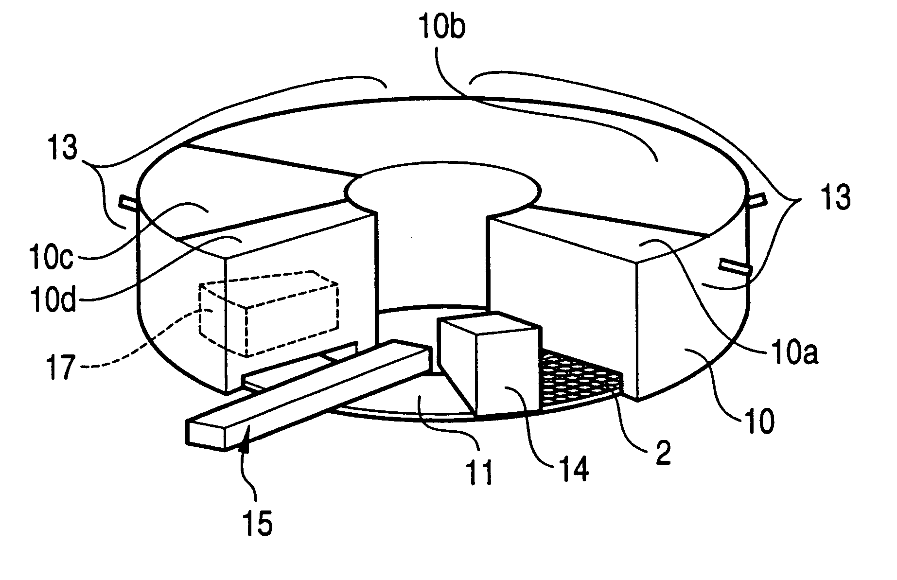
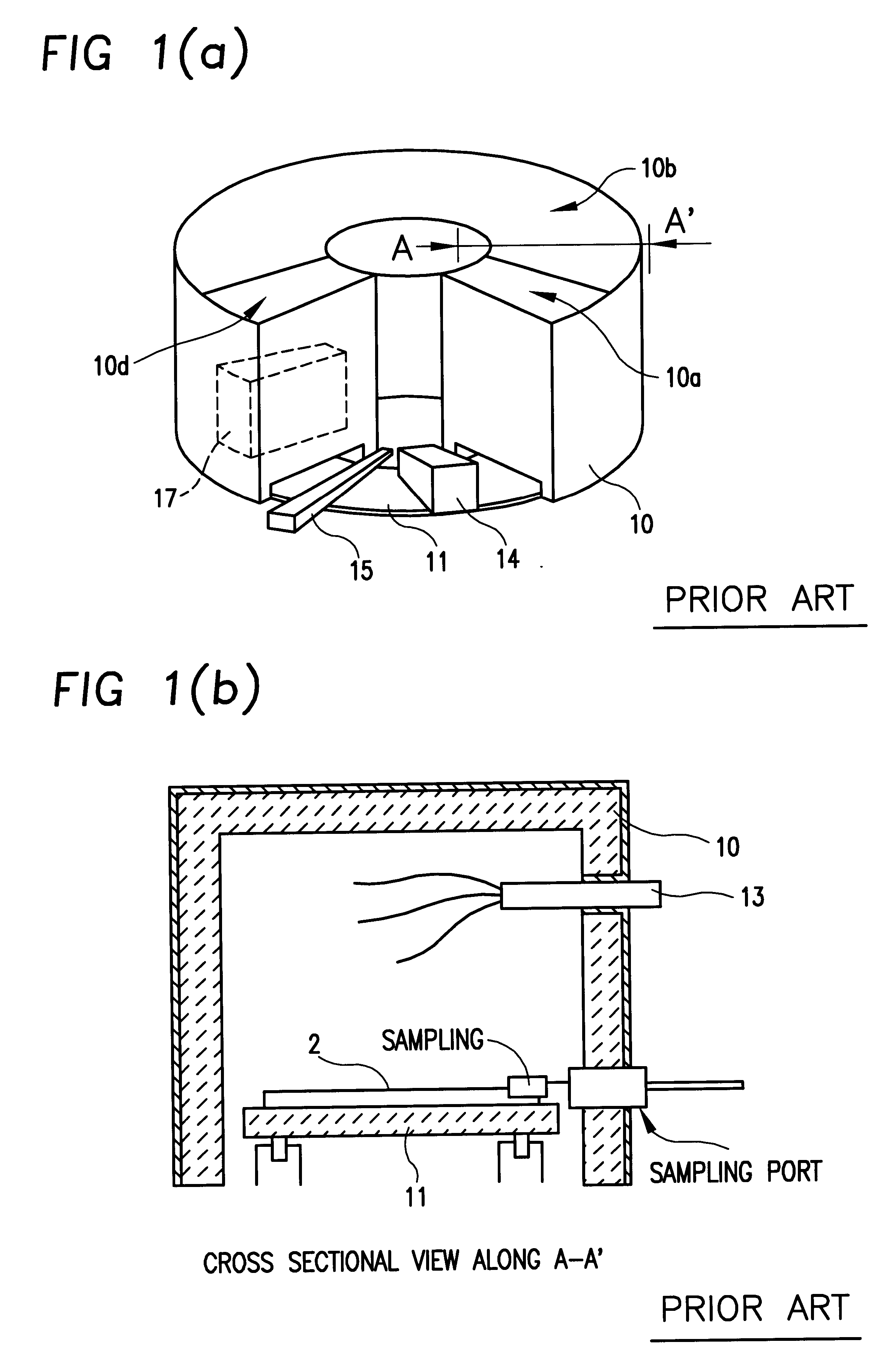
In this example, the operation described below was conducted using a rotary hearth furnace as shown in FIG. 7. The rotary hearth of 2.2 meter diameter was provided with an alumina refractory on the upper surface (as in FIG. 1(b)) and they were housed in an annular furnace body as in FIG. 1(b), in which a burner is disposed above the hearth.

As shown in FIG. 7, the hearth of the rotary furnace was divided into a preheating zone 10a, a reducing zone 10b, a melting zone 10c and a cooling zone 10d. A raw material layer 2 was formed on the rotary furnace hearth by charging and stacking a raw material mainly comprising an iron-containing material and a solid reducing material. In this facility, reference numerals identical with those shown in FIGS. 1(a) and 1(b) denote similar parts. The number 17 in FIG. 7 denotes a cooler disposed in front of a discharge port for cooling reduced iron and slag.

FIG. 8 is a schematic view taken near the furnace exit port used for the operation. After discha...

application example no.11

Application Example No. 11 involved lamination as in FIGS. 12(a) and 12(b), in which raw material 2 was placed in a layered shape on the hearth refractory 11 without any intervening solid reducing material layer. The reduced iron and the ash were melted for removing gangue and ash ingredients. Since the raw material was carried directly on the hearth refractory surface, the hearth refractory suffered from melting loss by molten materials. Further, some of the slag and the metal had large plate-like shapes that extended from the discharge port in the vicinity of the cooler 17 in FIG. 8. A crusher was disposed at a side of the discharge device and the products were crushed on the hearth before discharging to the outside of the furnace. Although the installation cost was increased by the installation of the crusher, and the running cost of electric power necessary for the operation of the crusher, and the cost regarding some melting loss of the hearth refractory material increased, the...

example 2

The following operation was conducted using the apparatus of Example 1. The raw material was charged and stacked at the supply port of the furnace by the charging device 14 on the rotary hearth 11 under the lamination condition shown in FIGS. 9(a) and 9(b) (Lamination Condition A). Limestone was added in an amount of 5% by weight into the solid reducing material layer 1. As shown in Table 5, it was found that the percentage of sulfur (S) was lowered in the recovered metal, in cases where limestone was blended with the solid reducing material layer, under substantially the same operation conditions.


PUM

PropertyMeasurementUnit
Massaaaaaaaaaa
Massaaaaaaaaaa
Massaaaaaaaaaa

Abstract

A traveling hearth for producing reduced metal by charging and stacking a raw material containing a metal-containing material and a solid-reducing material on a horizontally moving hearth, arranged for disposing a solid-reducing material layer on the hearth, forming concave portions at the solid-reducing material surface, stacking the raw material on the surface of the solid-reducing material layer, reducing the raw material by at least once heating and melting the material on the hearth to separate metal and gangue and ash ingredients, and discharging metal from the hearth.

Description

1. Field of the InventionThis invention concerns apparatus for of producing reduced and purified metal from a metal-containing raw and at least partially oxidized material. More particularly, this invention relates to an apparatus capable of a novel technique of charging and stacking metal-containing material on a hearth that is moving in a furnace, for heating and reducing the metal-containing material by heating during movement of the hearth. The apparatus at this invention continuously produces reduced metal of high quality from a traveling hearth furnace, with unexpected economy and efficiency.2. Description of the Related ArtSteels are generally produced either by a converter or an electric furnace. Electric furnace steels are produced by heating and melting scrap or reduced iron by using electrical energy, followed optionally by refining the same. However, since the supply of scrap has become scarce and the demand for high quality steels has increased more and more in recent y...

Claims


Application Information

Patent Timeline
IPC IPC(8): C22B5/00C22B5/10C21B13/00C21B13/10C22B1/16C22B1/216F27B9/16F27B9/30F27B9/36F27D3/12F27B9/00F27D7/06F27D7/00
CPCC21B13/0006C21B13/10C22B1/216C22B5/10F27B9/16F27B9/36F27D3/12F27D7/06F27M2001/18F27M2002/04F27M2003/13F27M2003/165C21B2100/44C21B2100/66Y02P10/20
Inventor SAWA, YOSHITAKAYAMAMOTO, TETSUYATAKEDA, KANJIITAYA, HIROSHI
Owner KAWASAKI STEEL CORP
Why Eureka
Try Eureka