

Optical fiber fixing member and method for manufacturing the same
a technology of optical fiber and fixing member, which is applied in the direction of glass making apparatus, manufacturing tools, instruments, etc., can solve the problems of increased connection loss, high production cost, and difficult mass production, and achieves high precision, high precision, and easy alignment.
- Summary
- Abstract
- Description
- Claims
- Application Information
AI Technical Summary
Benefits of technology
Problems solved by technology
Method used
Image

Examples
example 2 to example 8 (
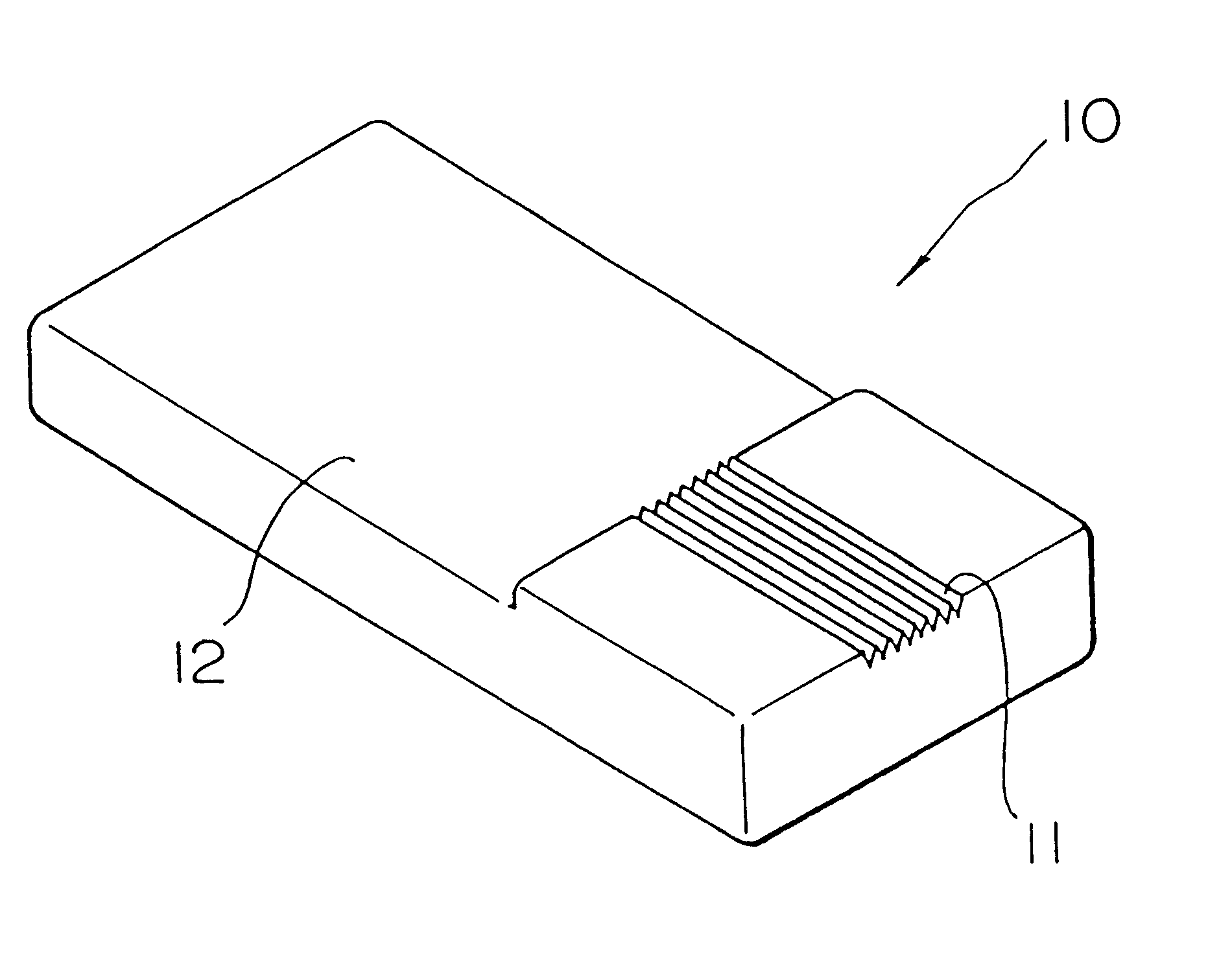
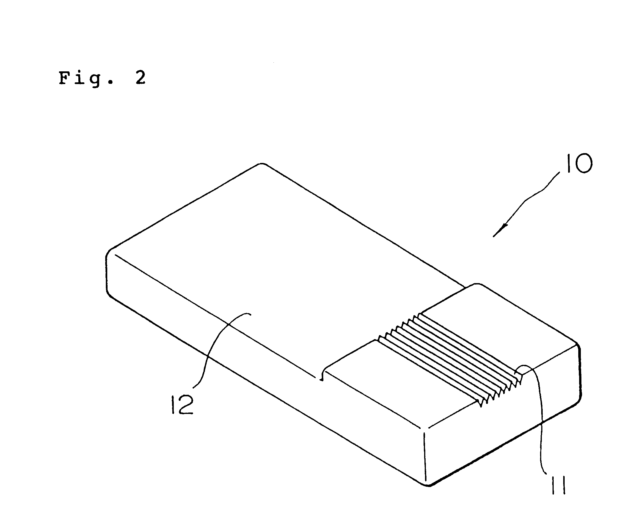
Production of optical fiber guide block)
A glass shaping preform having the same configuration as the glass shaping preform used in Example 1(1) was formed in each Examples 2 to 8 using a glass with respective compositions shown in Table 2 to obtain an optical fiber guide block by the same method as used in Example 1(1) except the molding temperature listed in Table 2 was adopted.
The dimensional and form accuracies of each optical fiber guide block obtained in each example were measured by the same method as used in Example 1(2), obtained the same results in Example 1(2).
The same results as in Example 1(3) were also obtained by continuous molding carried out under the same manner as in Example 1(3), in each example. Variance of the overall dimensions around the optical fiber fixing engagement portions among the molded articles was within .+-.0.9 .mu.m in all examples.
example 9
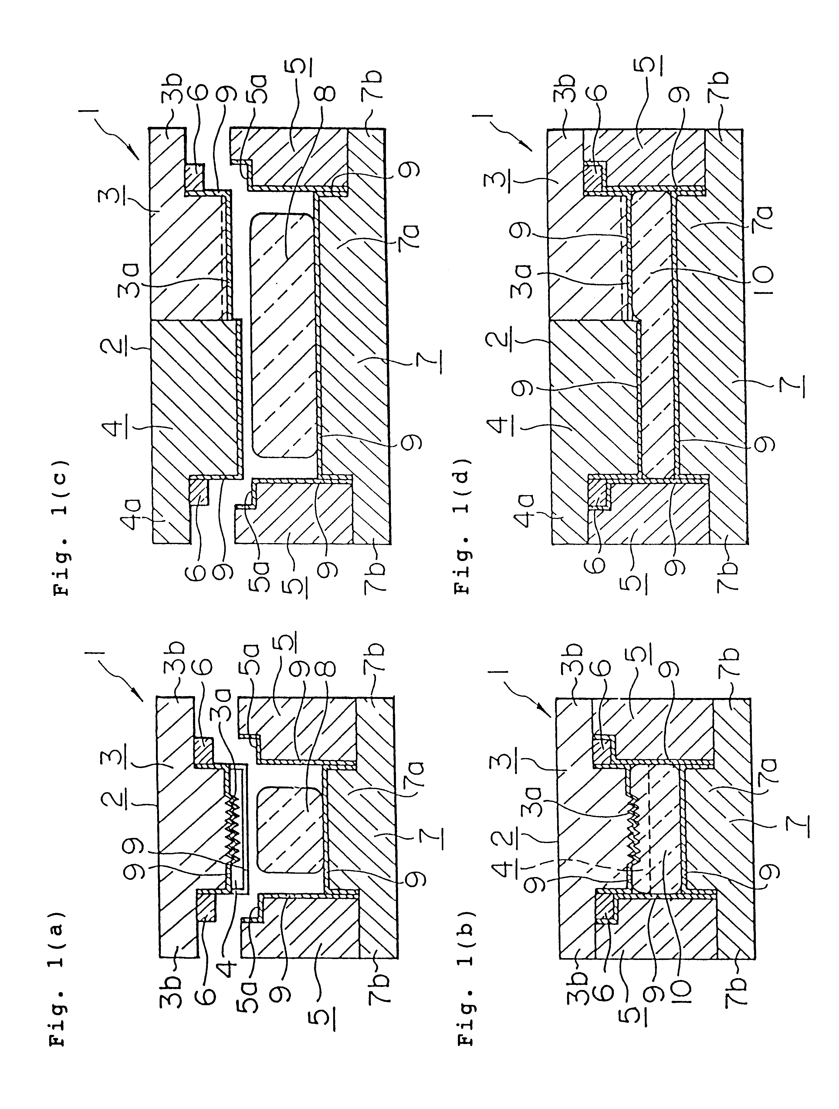
(1) Production of the Optical Fiber Guide Block
A glass shaping preform comprising the glass with the same composition as the glass material used in Example 1(1) with a dimension of 6.5.times.11.5.times.2.8 mm was produced by the same method as used in Example 1(1).
A mold having the same structure as the mold used in Example 1(1) was produced, except that the size of the upper and lower mold members was changed so that the width and length of the optical fiber guide block to be obtained are 8 mm and 13 mm, respectively, and the length of the optical fiber fixing engagement portions to be formed is 4 mm, a cermet (mean thermal expansion coefficient at a temperature of room temperature to 400.degree. C. is 88.times.10.sup.-7 / .degree. C. ) made of titanium carbide and titanium nitride was used for the mold material of the second molding part constituting the upper mold member, a carbon-based mold release film with a film thickness of 500 .ANG. formed by an ion plating method was used f...
example 10
(1) Production of the Optical Fiber Guide Block
A glass shaping preform comprising the glass with the same composition as the glass material used in Example 1(1) with a dimension of 3.5.times.10.5.times.2.8 mm was produced by the same method as used in Example 1(1).
A mold having the same structure as that of the mold used in Example 9(1) was produced, except that the configuration of the second molding part was changed so that the top faces of the side wall portions of the optical fiber guide block obtained are by 1 mm higher than the upper end face of the optical fiber fixing engagement portions, along with changing the dimensions of the upper, sleeve and lower mold members so that the width and length of the optical fiber guide block to be obtained are 5 mm and 12 mm, respectively and the length of the optical fiber fixing engagement portions to be formed is 5 mm.
An optical fiber guide block was thus obtained by the same method as in Example 1(1), except that the glass shaping pref...
PUM
| Property | Measurement | Unit |
|---|---|---|
| outer diameter | aaaaa | aaaaa |
| outer diameter | aaaaa | aaaaa |
| outer diameter | aaaaa | aaaaa |
Abstract
Description
Claims
Application Information