

Method and equipment for optical communication
a technology of optical communication and equipment, applied in the direction of electromagnetic transmission, digital transmission, transmission monitoring, etc., can solve the problems of difficult to realize exact compensation, the distortion of the pulse shape of the optical signal in the receiver, and the difficulty of achieving the effect of precise compensation
- Summary
- Abstract
- Description
- Claims
- Application Information
AI Technical Summary
Benefits of technology
Problems solved by technology
Method used
Image

Examples
Embodiment Construction
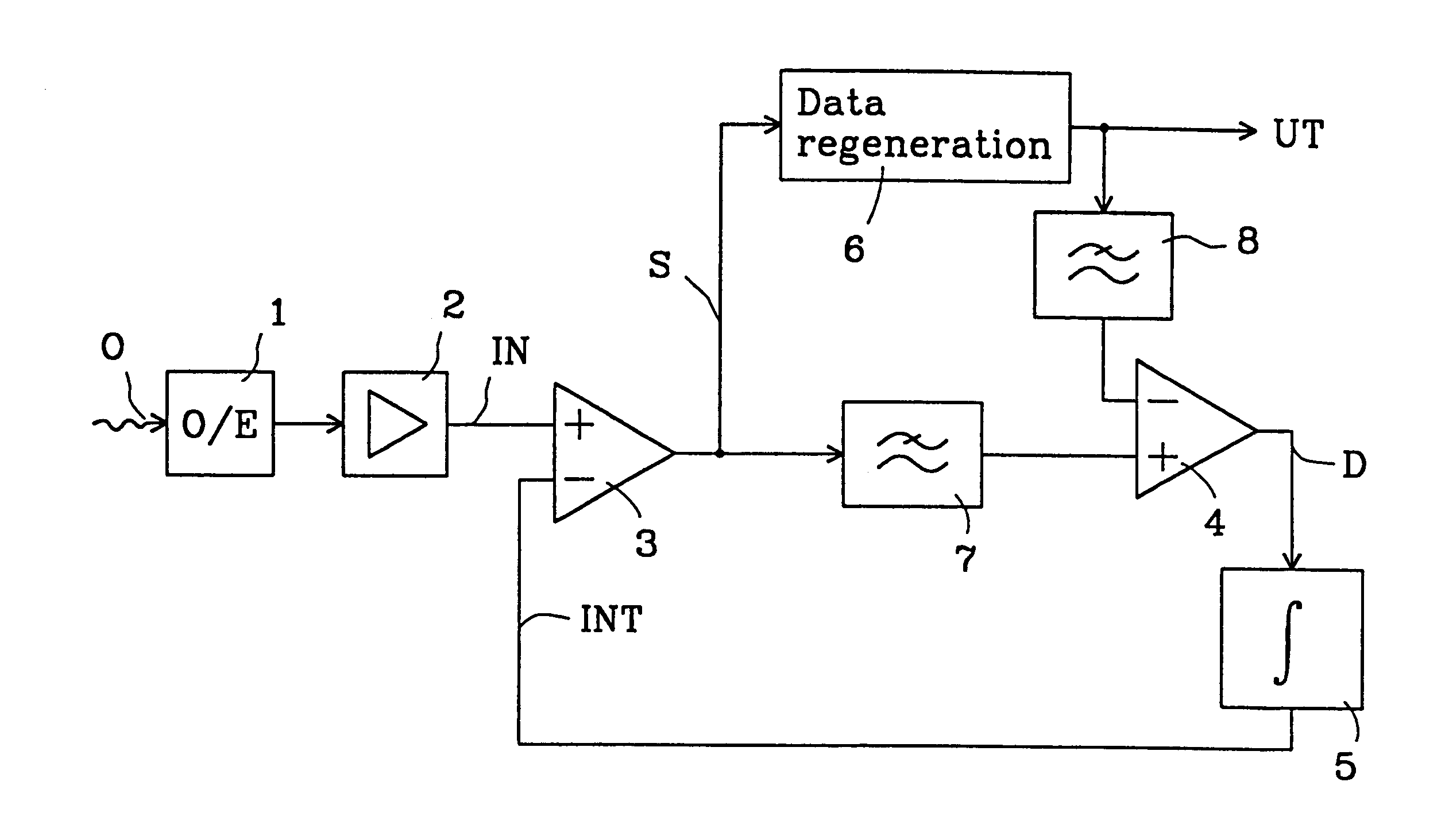
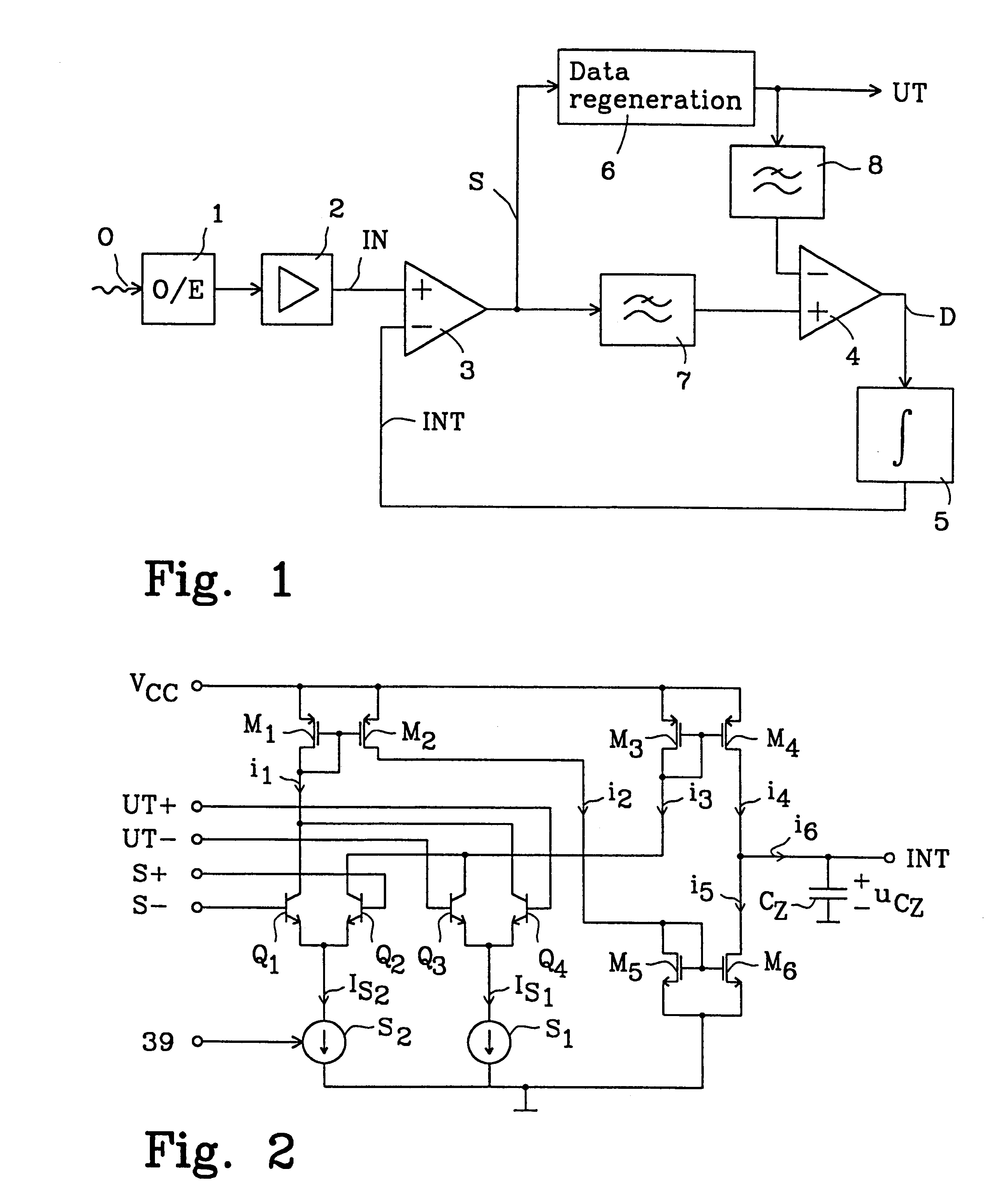
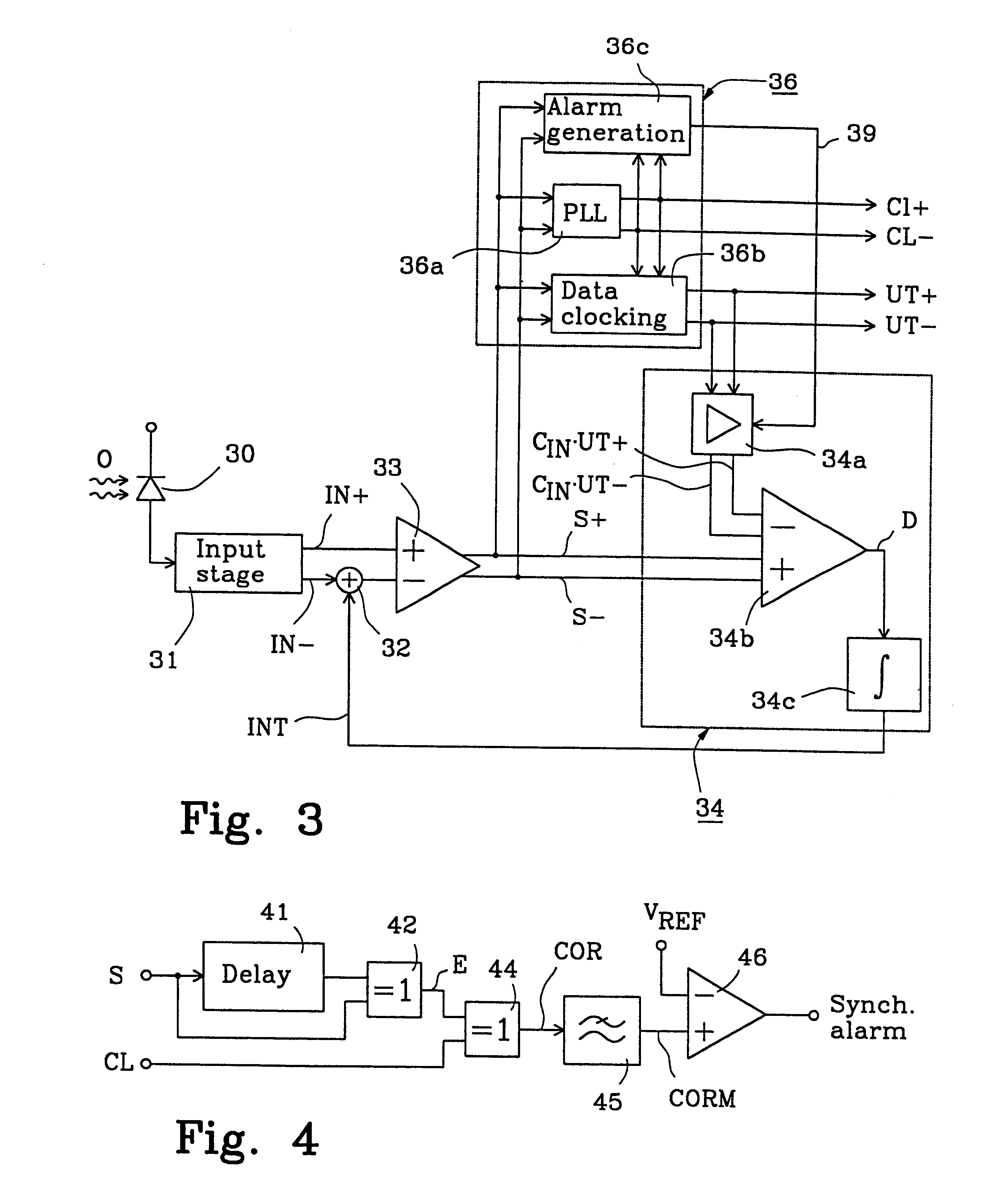
FIG. 1 depicts a block diagram for a fibre optic receiver according to a basic embodiment of the present invention.
An optical signal O is detected with an opto electrical converter 1 which is built-up according to known techniques and consists of a PIN-diode or an avalanche-photo diode (APD) with peripheral components. The opto electrical converter is followed by an amplifier stage 2 which converts the diode current from the opto electrical converter into a corresponding electrical voltage. The amplifier stage 2 furthermore contains a certain filtering. The resulting electrical signal IN out of the amplifier stage is superimposed onto a direct voltage. This signal is binarized with the help of a limiter 3 which acts as a decision circuit having the task of subtracting its two input signals, the signal IN and a comparison signal INT, and comparing the result with its decision threshold level and thereafter controlling its output signal, the binarized signal S, so that it has a high o...
PUM
 Abstract
Description
Claims
Application Information