
Fully integrated amplified loudspeaker

a fully integrated amplified loudspeaker technology, applied in the direction of transducer details, electrical transducers, cooling/ventilation/heating modification, etc., can solve the problems of inability to easily shield electromagnetic interference (emi) radiating components at low cost, the type of unit in reality is bulky and quite heavy, and the linearity of the entire amplified loudspeaker is improved, so as to achieve optimal matching of amplifier/driver electronics and improve the linearity

Inactive Publication Date: 2001-06-05
BILAN FRANK ALBERT +1
View PDF30 Cites 135 Cited by
  • Summary
  • Abstract
  • Description
  • Claims
  • Application Information

AI Technical Summary

Benefits of technology

Depending on the type of amplifier circuit utilized in an embodiment of this invention, there can be further added advantages. For example, if a class D amplifier were to be used, this invention provides distinct and unique advantages. A primary advantage is the ability to integrate the output stage filter inductor or inductors into the voice coil assembly. A further advantage is the virtual absence of EMI due to the inherent shielded construction of the traditional loudspeaker assembly. An additional advantage that class D amplifiers provide is the much higher and more efficient (approximately 90 percent) output drive capability provided. Thus, higher audio output power can be integrated into the voice coil assembly given similar amount of thermal energy to be removed than is possible using traditional linear amplifiers such as a class B amplifier, etc. The present invention is ideally suited to class D for the above reason and the inherent EMI shielding provided which are a bane to the high fidelity industry at present requiring expensive passive filtering.
Regardless of the type of amplifier utilized in an embodiment of the present invention, a further advantage is that the amplifier does not have to drive a pair of variable length heavy gage speaker wires. This allows the amplifier to be optimized for near zero length speaker wires and matched to the loudspeaker voice coil dynamic characteristics.
(e) allowing for optimal matching of the amplifier / driver electronics to the characteristic of the loudspeaker's voice coil;
(f) allowing for easy addition of various electronic circuitry and amplification stages to improve the linearity of the entire amplified loudspeaker;

Problems solved by technology

This type of unit, in reality, was bulky and quite heavy due to then available technologies, and is exemplified by Michael in U.S. Pat. No. 2,812,382.
However, the components are not self contained with in the loudspeaker itself, electromagnetic interference (EMI) radiating components cannot be easily shielded at low cost.
However, once again there is no easy way to inherently shield EMI radiating components within the assembly provided.
But this and similar arrangements do not inherently provide a way of achieving near zero length wiring connections between the loudspeaker and the amplifier / driver circuitry, providing EMI shielding for any EMI radiating components or reducing manufacturing costs.
While the prior art addresses various combinations of known technical issues, none address, greatly reduce or actually eliminate the cost of building and manufacturing multiple assemblies, the cost associated with heat dissipating hardware, the need to shield electromagnetic radiating components, as well as, other related technical issues.

Method used


Image

  • Fully integrated amplified loudspeaker
  • Fully integrated amplified loudspeaker
  • Fully integrated amplified loudspeaker

Examples


first embodiment

A schematic representation of the circuitry associated with the present invention is outlined in FIG, 3. FIG. 3 shows a traditional amplifier circuit, 30, utilizing integrated circuit, 32, connected in a class B bridge configuration along with other passive components driving voice coil, 45. Although a class B amplifier in a bridge configuration was chosen to eliminate large size electrolytic capacitors, it is possible to substitute other types or classes of amplifier circuit in any embodiment of the present invention.

Similarly, FIG. 4, shows a pictorial representation of amplifier circuit, 30. This particular embodiment of the present invention utilizes a very light and thermally conductive substrate material, 34, such as, Beryllium. The conductive substrate material, 34, is then overcoated on the component side with an appropriate insulating film or material followed by suitable metalization and the creation of electrically conductive traces and component pads.

Additionally, the su...

third embodiment

A third and more preferred sample embodiment of the present invention is shown in FIG. 8, FIG. 9, FIG. 10, and FIG. 11. In this third embodiment, the simple traditional amplifier circuit, 30, of the first sample embodiment is replaced with amplifier circuit, 230, utilizing an advanced class D amplifier to drive voice coil, 45, with higher efficiency.

In FIG. 10, a schematic representation of a typical class D amplifier circuit is shown. Of notable interest is the fact that class D based amplifier circuit, 230, attached to substrate, 234, shown in FIG. 11, requires inductive components, 40. A special cost advantage of the present invention is the ability to create inductive components, 40, by winding them onto former, 42, at the same time that voice coil, 45, is also wound onto former, 42. Inductive components, 40, are also generally of the power inductor type and can be relatively expensive and bulky. Mounting them on former, 42, along with voice coil, 45, eliminates the cost of thes...

tenth embodiment

the present invention is illustrated in FIG. 35, FIG. 36, and FIG. 37, in which a class D amplifier circuit, 930, with external inductive and capacitive (LC) filtering, is externally mounted on the back side of magnetic assembly, 905. Integrated circuit, 932, making up a portion of amplifier circuit, 930, is designed with a single ended output requiring only one inductive component, 940, and one capacitive component, 236. This circuit, however, requires an additional (negative) supply.

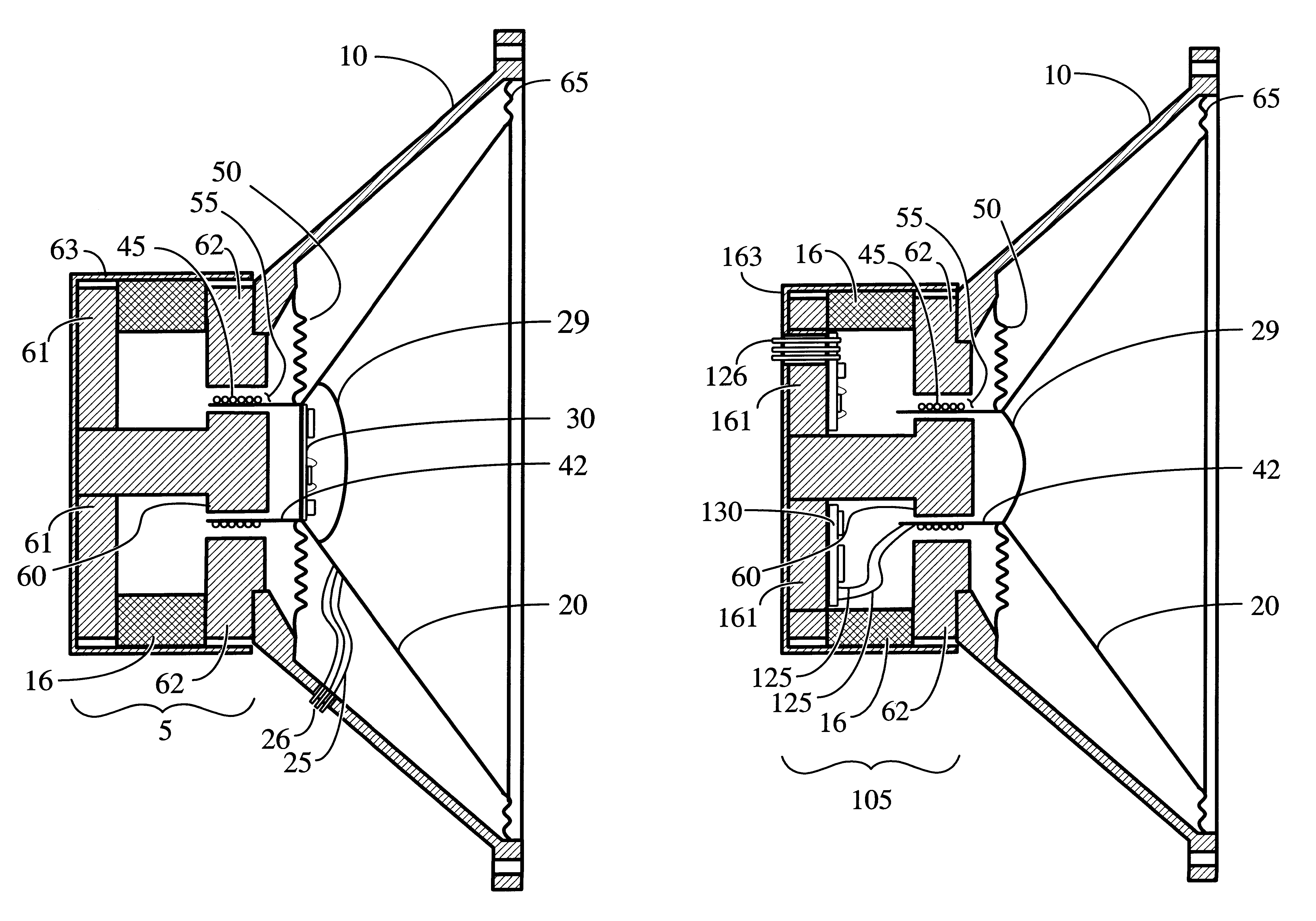
Connection to voice coil, 45, is made by way of tinsel wires, 125, through connector, 926, to amplifier circuit, 930. External power and input audio signal is provided to the amplified loudspeaker assembly through connector, 919. This embodiment shows the present invention in one of its simplest forms which proves to be very useful in that it fully shields the connection to voice coil, 45, from amplifier circuit, 930, such that any residual EMI radiation is further shielded by magnetic assembly, 905.

FI...


PUM

PropertyMeasurementUnit
Electrical conductivityaaaaaaaaaa
Magnetic fieldaaaaaaaaaa
Electrical conductoraaaaaaaaaa

Abstract

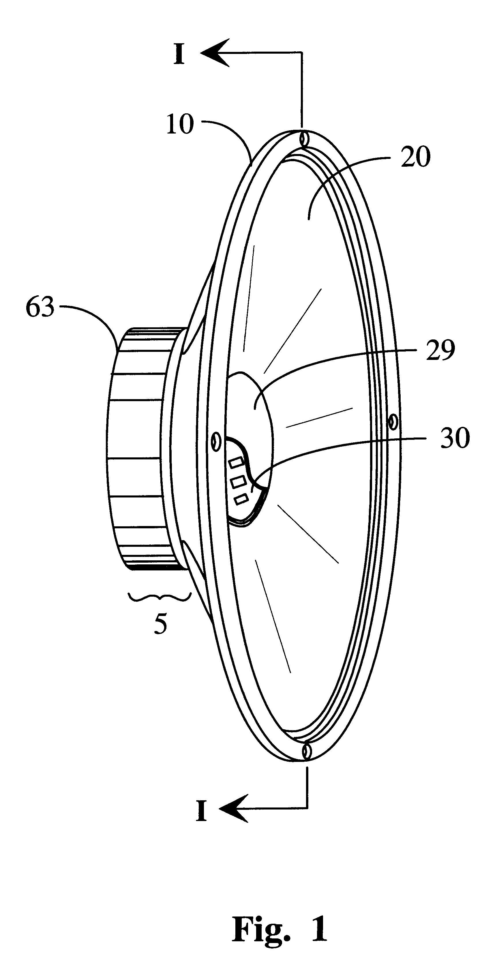
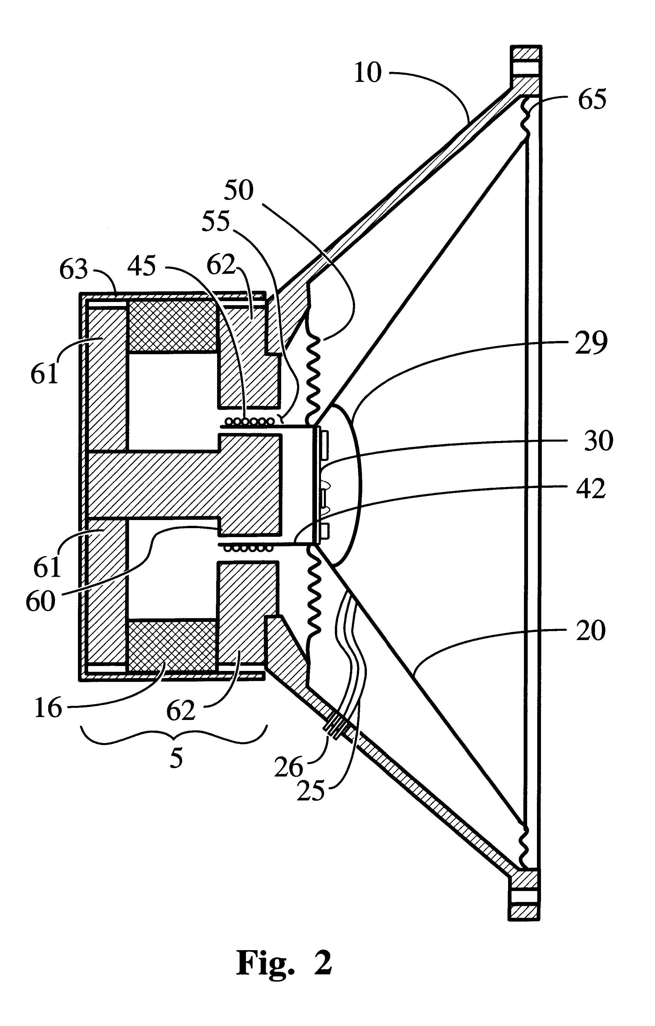
A fully integrated, low cost, amplified electro-acoustic loudspeaker is disclosed in which an amplifier circuit (30, 130, 230, 330, 930, 1030), radio-frequency receiver amplifier circuit (430, 530), optical receiver amplifier circuit (630, 730), or network based amplifier circuit (830) is directly mounted on the loudspeaker's magnetic assembly (105, 505, 705, 805), contained within the loudspeaker's moving assembly (20, 29, 629, 42, 45, 50, 65), or a combination thereof. The amplified loudspeaker's magnetic assembly (5, 105, 405, 505, 705, 805, 905, 1005) is utilized as an electro-magnetic interference shield and / or a heat dissipating element for the attached electronic circuitry. In selected embodiments of the amplified loudspeaker system, the former (42) containing voice coil (45) is additionally utilized for convection cooling of the amplifier circuit (30, 230) or receiver / amplifier circuit combination (430, 630).

Description

This invention relates to loudspeakers, and in particular, to electro-acoustic devices of the voice coil variety with built in amplification.The desire to build a single assembly containing a loudspeaker and an amplifier has existed since the birth of audio electronics. Early attempts focused on creating lighter weight portable combination chassis units that could be placed anywhere to provide amplified sound. This type of unit, in reality, was bulky and quite heavy due to then available technologies, and is exemplified by Michael in U.S. Pat. No. 2,812,382.With the miniaturization of electronic components came the desire to mount an entire power amplifier and related circuitry on the frame of a speaker. One of many such types of implementation is disclosed by Johnson et. al., in U.S. Pat. No. 5,164,991. In the Johnson patent, the goal was to provide variable amplification so as to permit a number of different types of line level signals to be connected to the amplifier rather than ...

Claims


Application Information

Patent Timeline
IPC IPC(8): H04R9/00H04R1/06H04R9/06
CPCH04R1/06H04R9/063Y10T29/49005H04R9/025
Inventor BILAN, FRANK ALBERTJELINEK, JULES JOSEPH
Owner BILAN FRANK ALBERT
Learn More