

Composite and its use
a technology of composite materials and composite materials, applied in the field of composite materials and their use, can solve the problems of affecting the final, affecting the interfacial region in question, and compromising the healing, and achieve the effect of rapid ossification and permanent integration of the implan
- Summary
- Abstract
- Description
- Claims
- Application Information
AI Technical Summary
Benefits of technology
Problems solved by technology
Method used
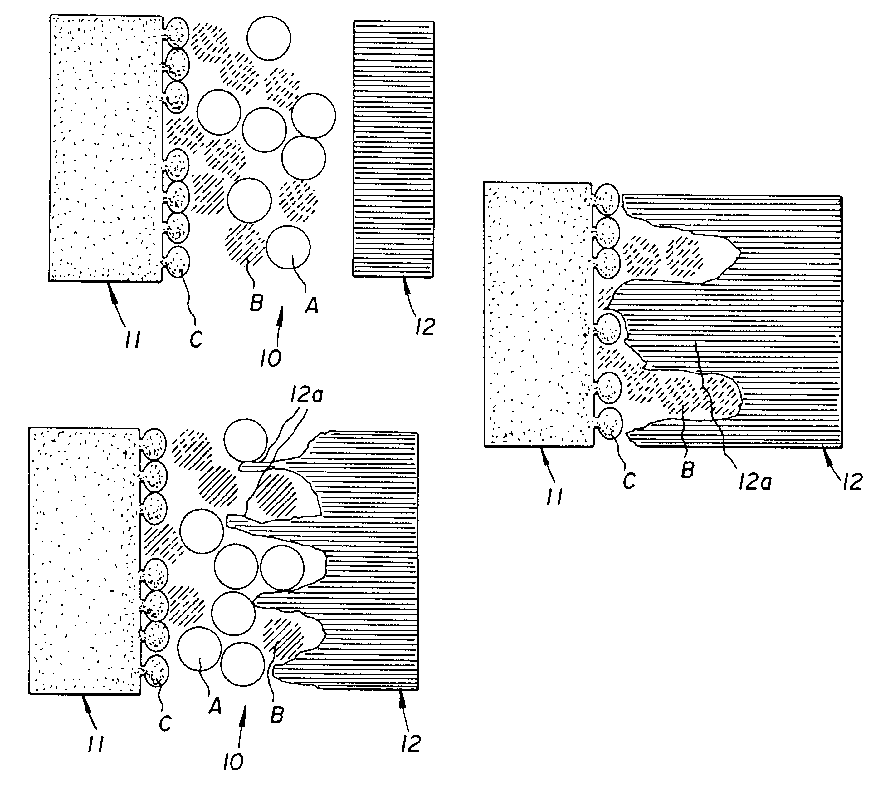
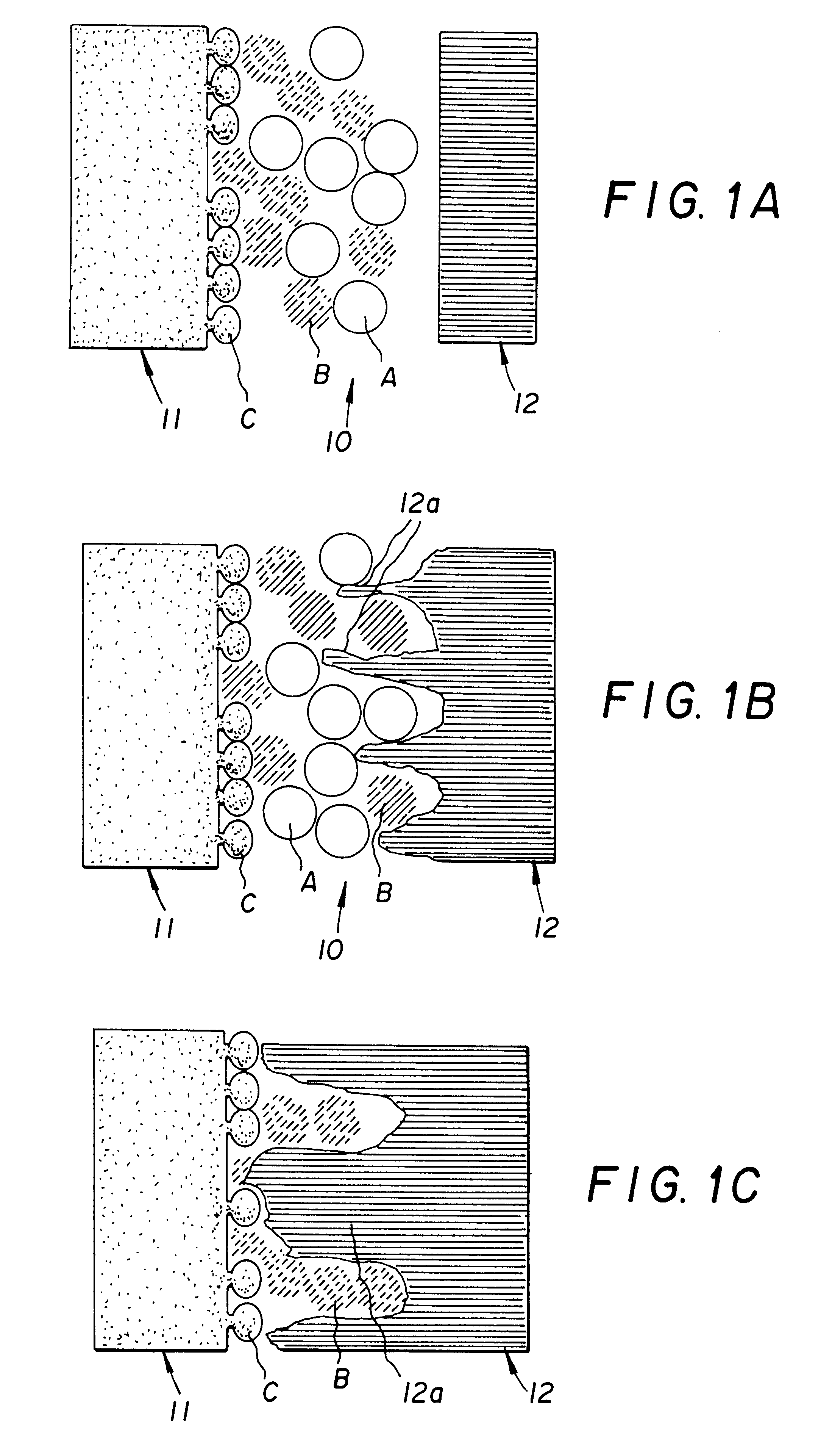
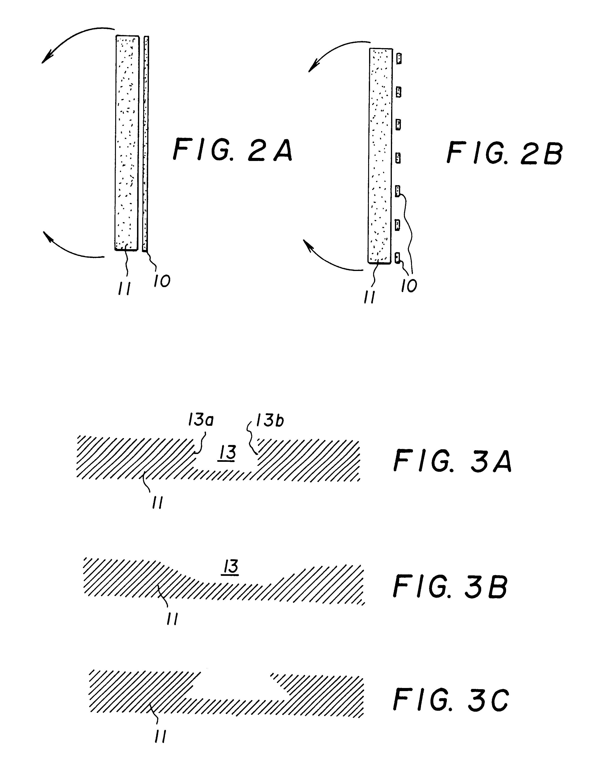
Image

Examples
example 1
Preparation of the Glasses
For the experiments described below, two types of glasses were prepared of which a was bioactive and b was very weakly bioactive. The glasses were prepared by mixing a paste from PA (pro analys) grade raw materials. The raw materials were Na.sub.2 CO.sub.3, K.sub.2 CO.sub.3, MgO, CaCO.sub.3, CaHPO.sub.4 *H.sub.2 O, H.sub.3 BO.sub.3 and fired SiO.sub.2. The composition of the prepared glasses is given in Table 2.
After weighing and mixing, the paste was melted in a platinum crucible at a temperature of 1360.degree. C. with a melting time of 3 hours. The glass melt was casted in a graphite mould into blocks which were cooled at 520.degree. C. for 30 minutes and subsequently in the oven, which was left to cool after switching the power off. The finished glasses were crushed and melted again in order to homogenize the glass mass. The glasses, which had been re-casted and cooled, were crushed and sieved into the 250-297 .mu.m fraction, whereafter the sieved crush...
example 2
Preparation of Glass Spheres
Using a torch spraying technique, the small glass particles were heated for a short time to a sufficient degree to have them melted and become rounded by virtue of the surface tension. After a quick cooling, the glass spheres were collected into a receptacle.
The torch spraying device used in the experiments comprised of a container for the crushed glass, a feeding tube, a common input head for the gases and crushed glass, and a nozzle. A mixture of acetylene and oxygen was used for heating. The nozzle was Castodyn 8000 nozzle nr. 30, which is intended for ceramic spraying. This nozzle gives a sufficient heat to round even the largest particles. The crushed glass flowed into the nozzle from the container above the device by its own weight. After a suitable mixing ratio has been found, the different quantity of heat required for the melting of different fractions can be controlled by adjusting the flow rate of the gases. Smaller particles melt faster than t...
example 3
Preparation of Glass-Based Cones
The implants used in the experiments described below were prepared by sintering glass spheres prepared according to the previous example into porous devices having the shape of a truncated cone. For the preparation of the glass cones, the glass spheres prepared from the glasses a and b of Table 2 were used. Two types of glass cones were prepared, type I and type II. The first type (I) of glass cones was prepared by sintering glass spheres which were torch sprayed from the glass a of Table 2. The second type (II) of glass cones was prepared by sintering a mixture of glass spheres of which 1 / 3 were glass spheres prepared from the glass a of Table 2 and 2 / 3 glass spheres prepared from the glass b of Table 2.
FIGS. 8A and 8B show an X-ray diffractometric analysis of a randomly chosen crushed cone. FIGS. 8A and 8B are X-ray diffractograms of the cone type I and the cone type II, respectively. It can be seen from these Figures that the glass has retained its...
PUM
| Property | Measurement | Unit |
|---|---|---|
| diameter | aaaaa | aaaaa |
| diameter | aaaaa | aaaaa |
| temperature | aaaaa | aaaaa |
Abstract
Description
Claims
Application Information