
Delta-sigma A/D converter

a converter and delta-sigma technology, applied in analogue/digital conversion, transmission systems, instruments, etc., can solve the problems of pipelined quantizers, inability to implement loop quantizers, and inability to achieve the maximum sampling frequency

Inactive Publication Date: 2001-08-07
ANALOG DEVICES BV
View PDF6 Cites 139 Cited by
  • Summary
  • Abstract
  • Description
  • Claims
  • Application Information

AI Technical Summary

Benefits of technology

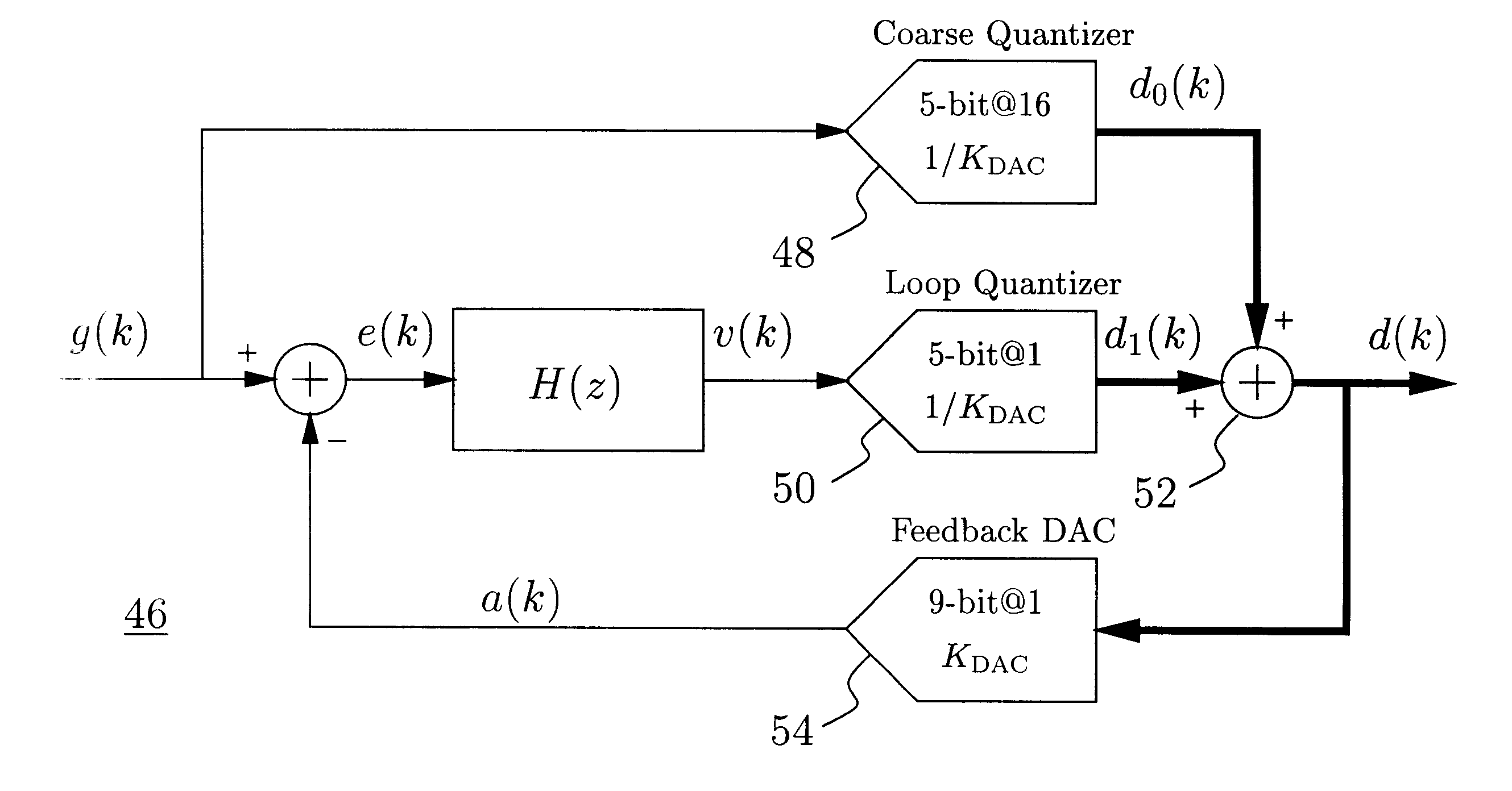
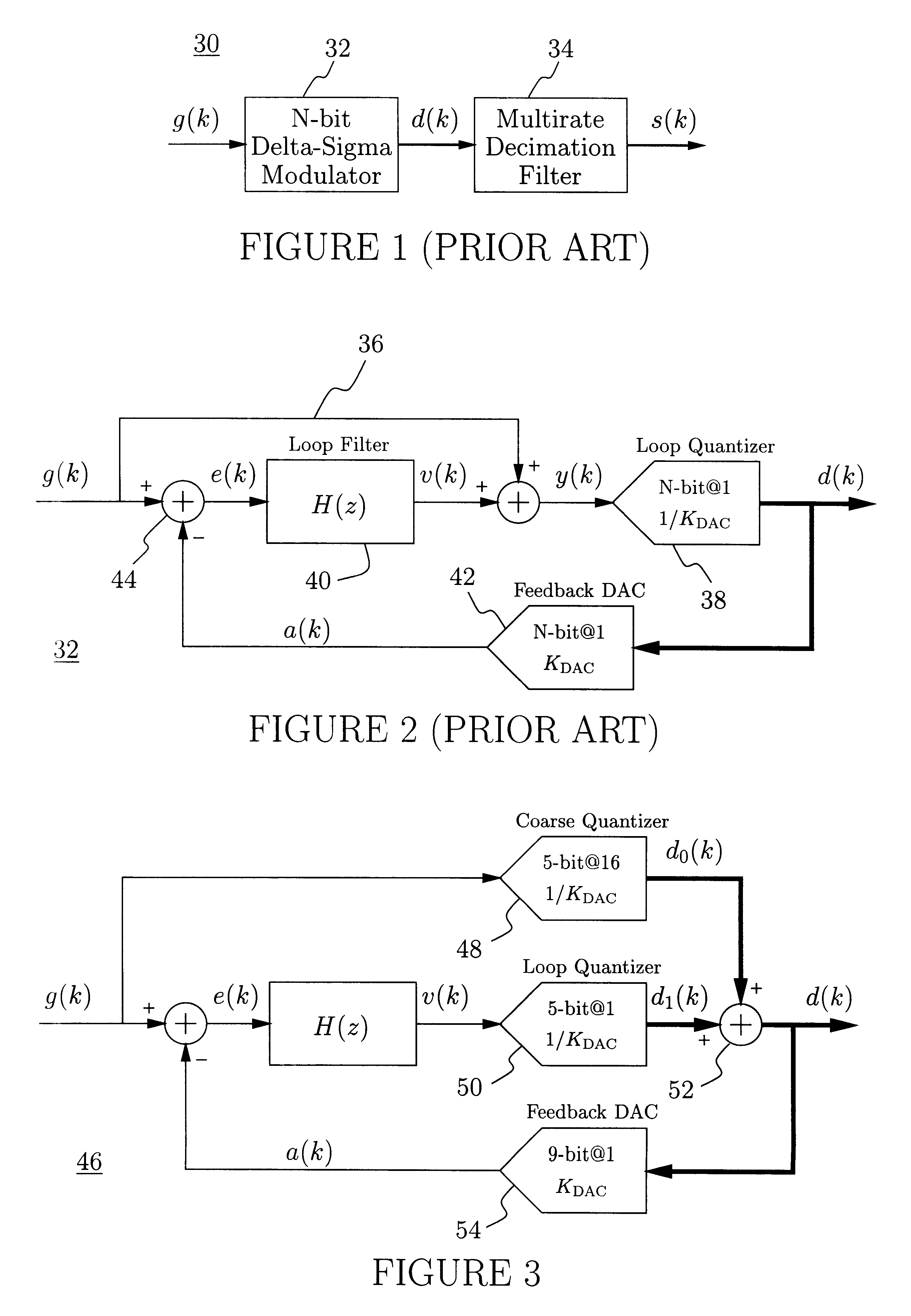
A delta-sigma modulator according to this invention comprises a pipelined multi-step quantizer quantizing the sum of the input signal g(k) and the loop filter's output signal v(k). Only the multi-step quantizer's last stage is used to quantize the loop filter's output v(k), thus adding only very little to the loop delay. The loop filter is implemented as a multi-path mixed-delay feedback structure allowing the feedback DAC several clock cycles of latency without compromising the modulator's stability.
to provide a stable delta-sigma modulator structure in which a pipelined multi-step quantizer is used for the generation of a high-resolution output signal;
to provide a stable delta-sigma modulator structure for which the latency of the critical feedback DAC may be several clock cycles, thus facilitating the use of low-power digital circuitry to implement mismatch-shaping algorithms in high-speed delta-sigma ADCs;
to provide a simple delta-sigma modulator structure providing a high-resolution output signal;
to provide a delta-sigma A / D converter system for which the decimation filter can be greatly simplified, thus reducing the overall power consumption;
to provide a delta-sigma modulator structure optimized such that critical operations are allowed latency, and such that low-latency operations may cause relatively large errors without significantly deteriorating the overall performance.

Problems solved by technology

The complexity of these mismatch-shaping circuits unfortunately becomes impractically high when the resolution N is significantly higher than (say) 6 bits.
High-resolution quantizers are most easily implemented as multi-step quantizers, but their throughput (i.e., the maximum sampling frequency) is relatively low unless pipeline techniques are employed.
Pipelined quantizers, however, cannot be used to implement the loop quantizer [38] because their delay will make the closed-loop delta-sigma modulator [32] unstable.
Mismatch-shaping DACs require that some numerical computations be performed, which will further increase the loop delay.

Method used


Image

  • Delta-sigma A/D converter
  • Delta-sigma A/D converter
  • Delta-sigma A/D converter

Examples


fourth embodiment

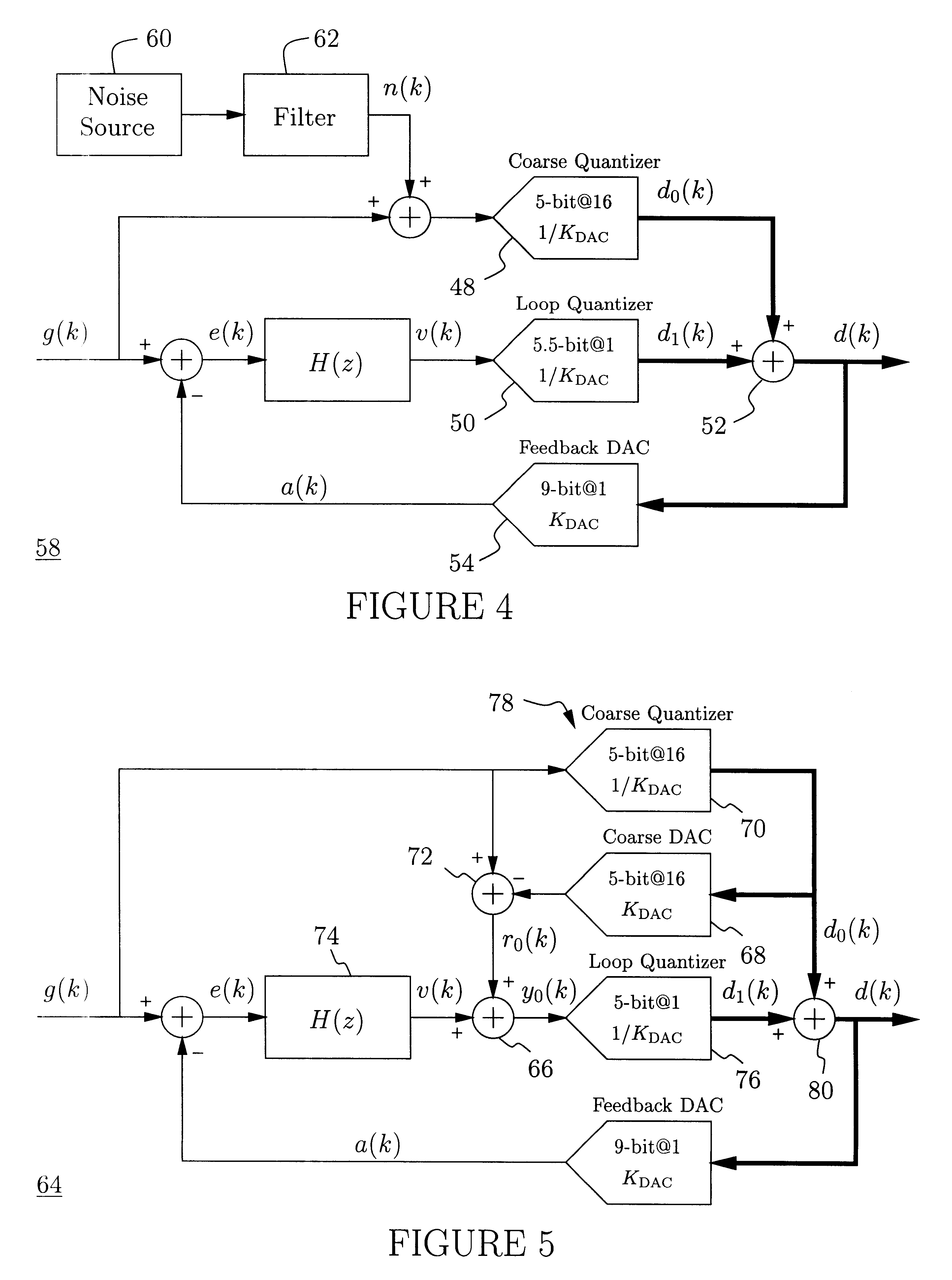
Although the modulator [46] shown in FIG. 3 per se is very useful for moderate-to-highly oversampled applications, it is generally preferable to avoid the distortion in d.sub.0 (k), e.g., by dithering the coarse quantizer [48]. This simple technique can be implemented as shown in FIG. 4. A noise signal n(k) is added to g(k), and the sum is quantized by the coarse quantizer [48]. The noise signal's n(k) magnitude should be approximately as large as the coarse quantizer's [48] LSB, i.e., 16.multidot.K.sub.DAC, and the loop quantizer's [50] resolving range must be increased accordingly. It is preferable if n(k) has only little power in the signal band. The desired spectral composition of n(k) can be obtained using a broadband noise source [60] followed by a filter [62] suppressing the undesired (signal-band) spectral components. The noise source [60] and the filter [62] can, for example, be implemented as a digital noise-shaping loop and a simple DAC (not shown). A better technique is ...

third embodiment

FIG. 26 shows the main delta-sigma modulator [234]. It comprises a third-order loop filter [270] of the same type [198] as shown in FIG. 23 and discussed above. The feedback delays, T.sub.d3, T.sub.d2, T.sub.d1, T.sub.d0, and the feedback coefficients, b.sub.3, b.sub.2, b.sub.1, b.sub.0, are the same as used for the third embodiment [196] discussed above.

The two least critical feedback signals are generated using an analog feedback circuit [272] similar to that [260] used for the coarse delta-sigma quantizer [228]. Clearly, the feedback coefficients, b.sub.3, b.sub.2, b.sub.1, b.sub.0, are not the same as those used for the coarse delta-sigma quantizer [228]; the loop filters are of different orders.

The two most critical feedback signals are generated by D / A converting the digital compensation signal d.sub.1 (k). The most critical DAC [274] makes use of a first-order mismatch-shaping algorithm and a deglitching output stage, whereas the second-most critical DAC [276] uses only a deg...


PUM


Abstract

A delta-sigma modulator comprising a first quantizer providing a first digital signal d0(k) representing the input signal g(t); a loop filter with input signal paths; a loop quantizer providing a corrective digital signal d1(k) representing the loop filter's output signal y(t); an array of feedback DACs D / A converting the sum d(k)=df(k)=d0(k)+d1(k) of the first and the corrective digital signals and injecting feedback signals into the loop filter.The loop filter's input node is applied the difference of the input signal g(t) and the global analog feedback signal a3(t). The global feedback signal a3(t) is delayed several clock cycles with respect to the digital output signal d(k). The delay is used to carry out mismatch-shaping and deglitching algorithms in the feedback DACs. The feedback DACs' different delays and gain coefficients are designed such that the modulator is stable. The filter's input signal paths and the compensating DAC are designed such that the gain from the input signal g(t) to the loop quantizer is small, ideally zero. Thus, the loop quantizer's resolving range can be a fraction of the first quantizer's resolving range, whereby the output signal's d(k) resolution can be much higher than the individual resolutions of d0(k) and d1(k).The delta-sigma modulator is well suited for the implementation of high-resolution wide-bandwidth A / D converters. Important applications include digital communication systems.

Description

1 FIELD OF INVENTIONThe field of invention is data conversion, more particularly, this invention relates to oversampling analog-to-digital converters.2 DESCRIPTION OF PRIOR ARTDelta-sigma modulation has been used successfully for the implementation of high-resolution A / D converters. The general concept is shown in FIG. 1. The analog input signal g(k) is converted to a digital representation d(k) using an N-bit delta-sigma modulator [32]. The resolution N of d(k) is lower than the A / D converter system's [30] effective resolution, but the sampling frequency of d(k) is comparably higher than twice the system's [30] bandwidth, i.e., d(k) is an oversampled signal. A signal's sampling frequency divided by twice the system's [30] bandwidth is called the signal's oversampling ratio OSR, which is always greater than one. Thus, d(k) is not an accurate representation of g(k) on a sample-to-sample basis, but a good delta-sigma modulator [32] will ensure that the spectral composition of g(k) and...

Claims


Application Information

Patent Timeline
IPC IPC(8): H03M1/14H03M3/04H03M3/00
CPCH03M3/46H03M3/416H03M1/167H03M3/424H03M3/42
Inventor STEENSGAARD-MADSEN, JESPER
Owner ANALOG DEVICES BV
Learn More