Chlorinated hydrocarbon waste incinerator and valorization of chlorinated residuals process unit

a technology of chlorinated hydrocarbon and incinerator, which is applied in the direction of emissions prevention, combustion types, separation processes, etc., can solve the problems of undesirable n.sub.2/co.sub.2 vent stream and inefficient operation

Inactive Publication Date: 2001-08-14
TAYLOR TIMOTHY LYLE +2
View PDF9 Cites 7 Cited by
  • Summary
  • Abstract
  • Description
  • Claims
  • Application Information

AI Technical Summary

Benefits of technology

However, the inventor has surmised that a synthesized mixture of roughly twenty-one (21%) percent by volume O.sub.2 and seventy-nine (79%) percent by volume CO.sub.2 could be used in place of air in both the chlorinated hydrocarbon waste incinerator and the VCR reactor, thereby eliminating the undesirable N.sub.2 from the vent stream. This synthesized gas mixture could contain as much as ninety (90%) percent by volume CO.sub.2 and ten (10%) percent by volume O.sub.2, or as little as twenty-five (25%) percent by volume CO.sub.2 and seventy-five (75%) percent by volume O.sub.2. However, the optimum mixture would likely contain from about sixty (60%) percent to about eighty (80%) percent by volume CO.sub.2, with forty to twenty (40% to 20%) percent by volume O.sub.2 comprising the remaining percentage.
CO.sub.2, an inert gas, could essentially replace the diluent N.sub.2 in the feed air, thus providing the same diluent and non-reacting properties of the N.sub.2. The O.sub.2 in this mixture, essentially the same amount by volume as found in air, would effectively carry out the reaction with the chlorinated organic intermediates necessary to break down these chlorinated molecules, as in the incinerator, or to produce anhydrous HCl, as in the VCR reactor. The by-products of the reaction would therefore be comprised essentially of CO.sub.2 and a small amount of O.sub.2. Trace amounts of Cl.sub.2 and HCl in these emissions would still be eliminated in the alkaline scrubbing unit attached to either system, thereby producing a harmless salt water by-product. Other unwanted trace compounds, such as dioxin, can be eliminated from the vent gases through modifications that are described below. The remaining vent gas emission would therefore be predominately CO.sub.2 and a small amount of O.sub.2. In this way, no undesirable N.sub.2 would enter or leave the incinerator or the VCR process unit. The reaction employing a CO.sub.2 / O.sub.2 mixture in place of air in the VCR process unit is shown in FIG. 6. The modified system using only the CO.sub.2 / O.sub.2 mixture is depicted in FIG. 7. The modified waste incinerator is depicted in FIG. 8.
A further advantage exists in using CO.sub.2 as a diluent in the gaseous raw material fed into the VCR process unit and into the chlorinated hydrocarbon waste incinerator. Since CO.sub.2 is a necessary inert component to this raw material, the CO.sub.2 that comprises the final emission from either system could then be reclaimed and reused to mix with O.sub.2 as the diluent in the gaseous raw material. In this way, the VCR process unit genuinely becomes a "closed-system." wherein all end-products of the VCM and VCR processes are reused in the system.

Problems solved by technology

Since CO.sub.2 is an identified greenhouse-effect gas, and since the separation and purification of N.sub.2 and CO.sub.2 in this vent stream would be a very expensive and an inefficient operation, the N.sub.2 / CO.sub.2 vent stream is undesirable.

Method used


Image

  • Chlorinated hydrocarbon waste incinerator and valorization of chlorinated residuals process unit
  • Chlorinated hydrocarbon waste incinerator and valorization of chlorinated residuals process unit
  • Chlorinated hydrocarbon waste incinerator and valorization of chlorinated residuals process unit

Examples


Embodiment Construction

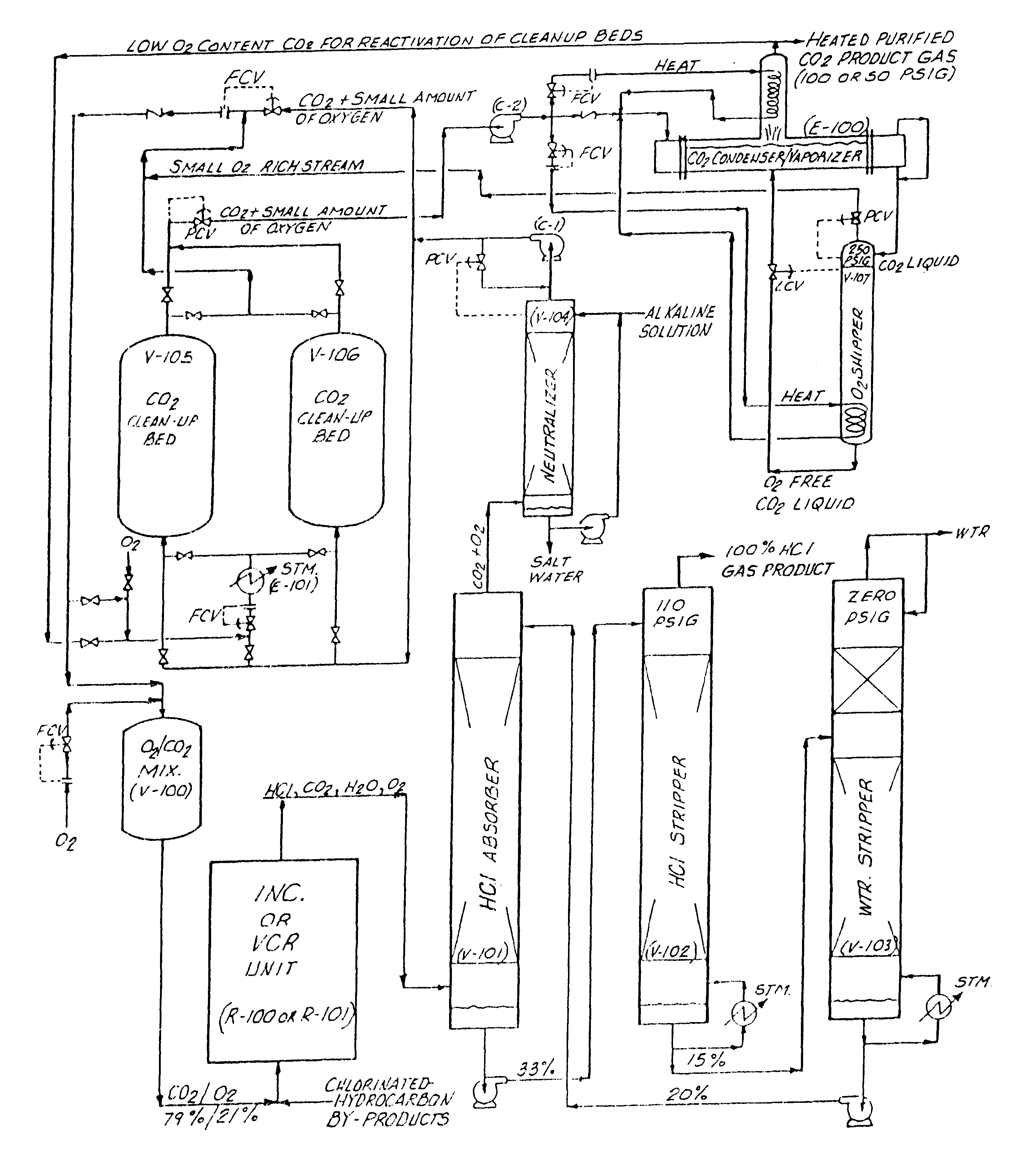
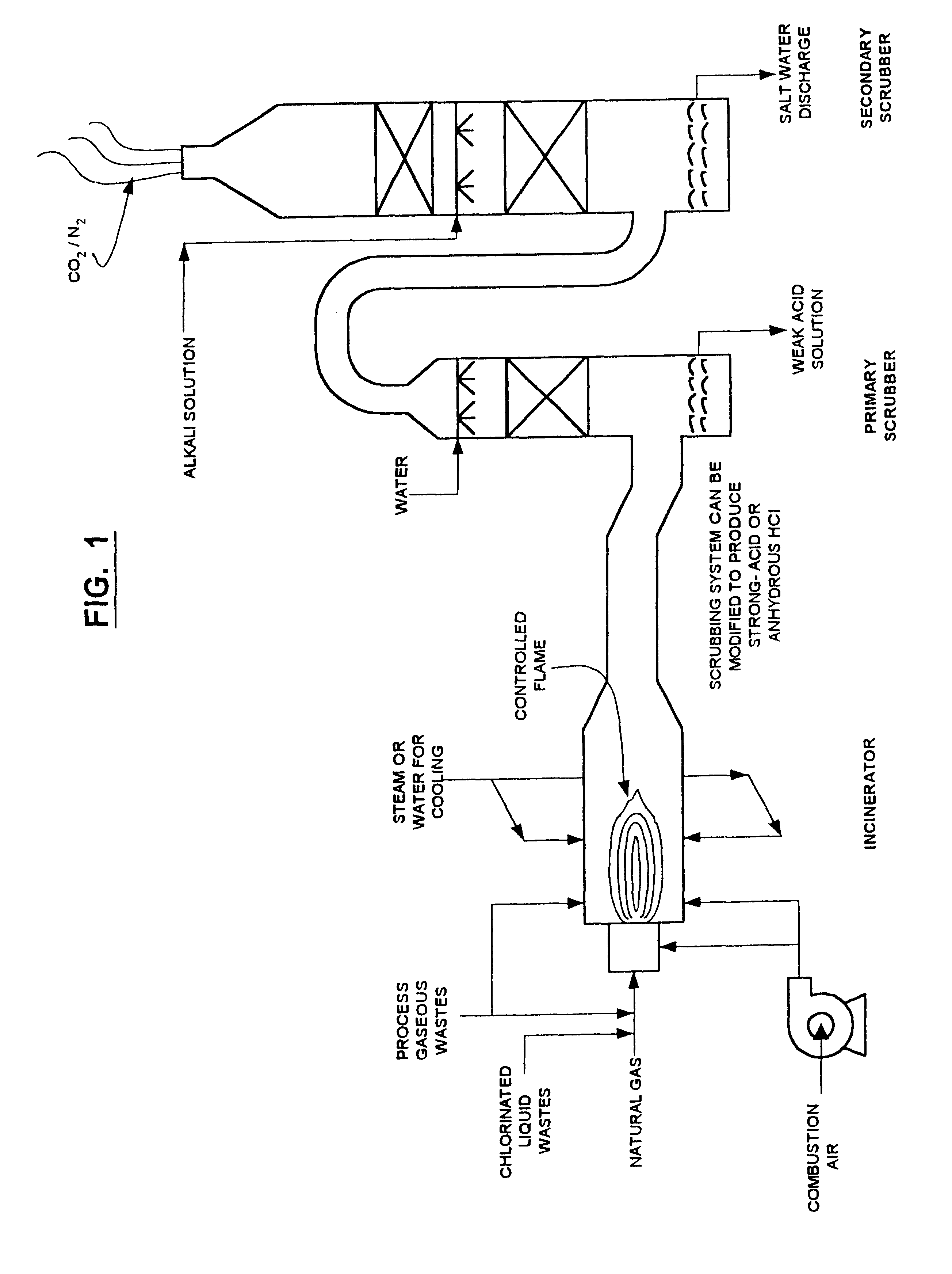
FIG. 1: The typical chlorinated hydrocarbon waste incinerator system is shown. The system is comprised of a central, high-temperature incinerator into which natural gas, chlorinated liquid wastes and process gaseous wastes are injected, along with combustion air. The controlled natural gas flame burns within the incinerator. There is a port adjacent to this flame wherein steam or water can be injected to cool the reaction. A primary scrubber is attached downstream of the incinerator, wherein hydrogen chloride is dissolved in water to produce a weak acid solution. A secondary scrubber containing an alkali solution is attached downstream of the primary scrubber in order to neutralize any HCl or chlorine still contained in the vent gas. The remaining CO.sub.2 / N.sub.2 gas is vented from this secondary scrubber.

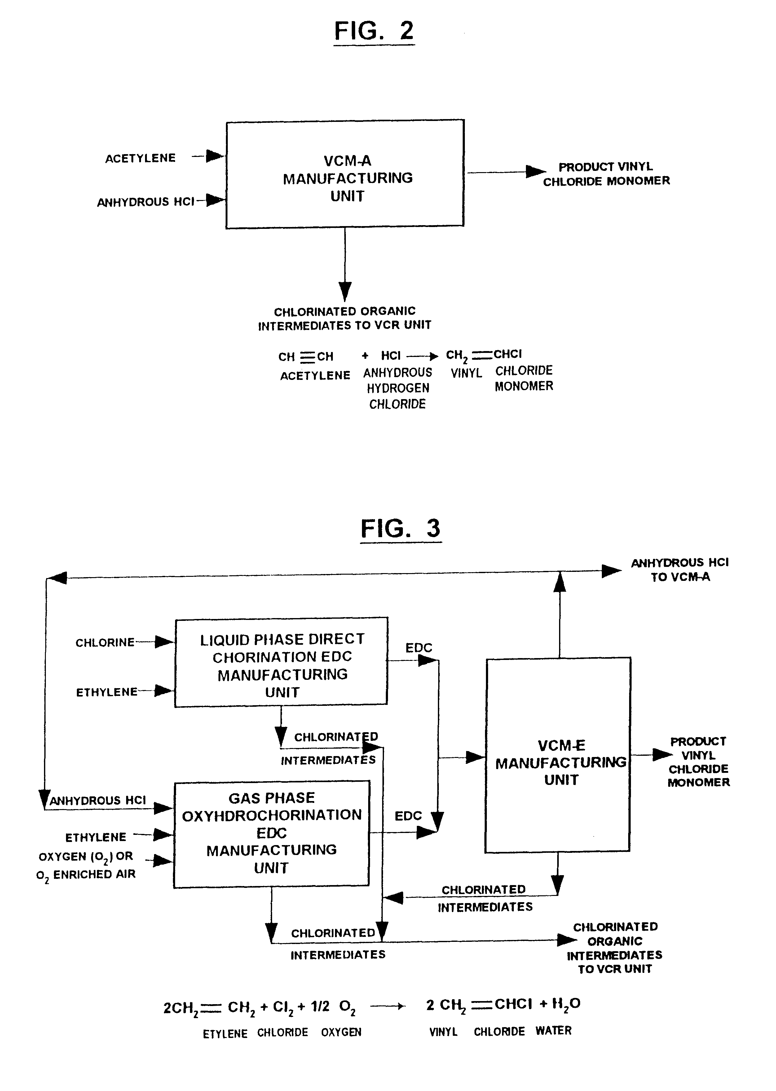
FIG. 2: The reaction taking place in a vinyl chloride monomer-acetylene (VCM-A) manufacturing unit is depicted. In this unit, acetylene is reacted with anhydrous HCl to produce v...


PUM

PropertyMeasurementUnit
concentrationaaaaaaaaaa
pressureaaaaaaaaaa
weightaaaaaaaaaa

Abstract

A closed-loop process for incinerating chlorinated hydrocarbon-containing material without the emission of air borne pollutants. The chlorinated hydrocarbon-containing material is incinerated, preferably in the substantial absence of air, thereby producing a gaseous effluent containing hydrogen chloride and pollutants such as carbon dioxide, acid gases, and halogenated compounds. The gaseous effluent is passed through a hydrogen chloride purification system to remove hydrogen chloride from the gaseous effluent and to produce a concentrated anhydrous hydrogen chloride gaseous stream. The gaseous effluent is passed through at least one sorbent bed, such as a bed of activated carbon, to remove halogenated pollutants from the effluent. The pollutants are desorbed from the one or more sorbent beds and recycled to the incinerator where they are decomposed by combustion.

Description

The present invention relates to an improved method for treating chlorinated hydrocarbons in valorization of chlorinated residuals (VCR) process unit (see, e.g., U.K. Pat. No. GB 2053452) and the chlorinated hydrocarbon waste incinerator, and more particularly to a method for modifying these systems such that a synthesized blend of carbon dioxide and oxygen replaces the ordinary air used to fuel the reaction in either system, thereby generating a useful hydrogen chloride product and a useful carbon dioxide product in both the VCR process unit and the chlorinated hydrocarbon waste incinerator. The invention further encompasses modifications to the anhydrous hydrogen chloride purification unit attached to these systems that prevent the discharge of any hydrochloric acid streams containing three (3%) percent by weight or greater hydrogen chloride dissolved in water. Furthermore, the invention encompasses the addition of absorbent beds to these systems that remove contaminants from the ...

Claims


Application Information

Patent Timeline
Patent Type & Authority Patents(United States)
IPC IPC(8): C01B7/00C01B7/03C01B7/07F23G5/027F23G7/06F23G7/12
CPCC01B7/035C01B7/0706F23G5/0276F23G7/065F23G7/12F23J2219/80F23G2207/103F23G2209/141F23J2215/301F23J2219/30F23J2219/60F23G2206/10
Inventor TAYLOR, TOMMY G.
Owner TAYLOR TIMOTHY LYLE
Why Eureka
Try Eureka