Microdosing device and method for operating same

Inactive Publication Date: 2001-08-28
ZYRUS BET GMBH & CO PATENTE I KG
View PDF14 Cites 222 Cited by
  • Summary
  • Abstract
  • Description
  • Claims
  • Application Information

AI Technical Summary

Problems solved by technology

The limited dosing accuracy in the case of smaller volumes is predominantly due to the fact that the tip of the pipette or dispenser must be immersed in the medium to be dosed, whereby the dosing amount is influenced by effects such as surface tension, wetting and hydrostatic pressure.
Furthermore, generation of drops is only possible in a very limited viscosi

Method used


Image

  • Microdosing device and method for operating same
  • Microdosing device and method for operating same
  • Microdosing device and method for operating same

Examples


Embodiment Construction

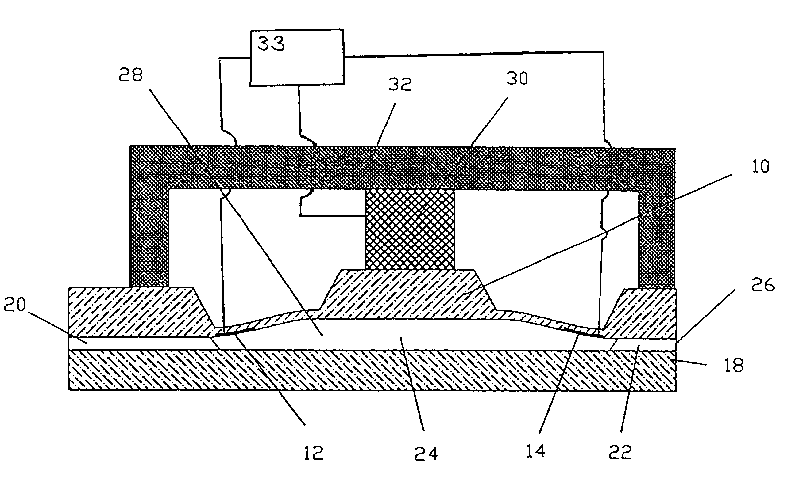
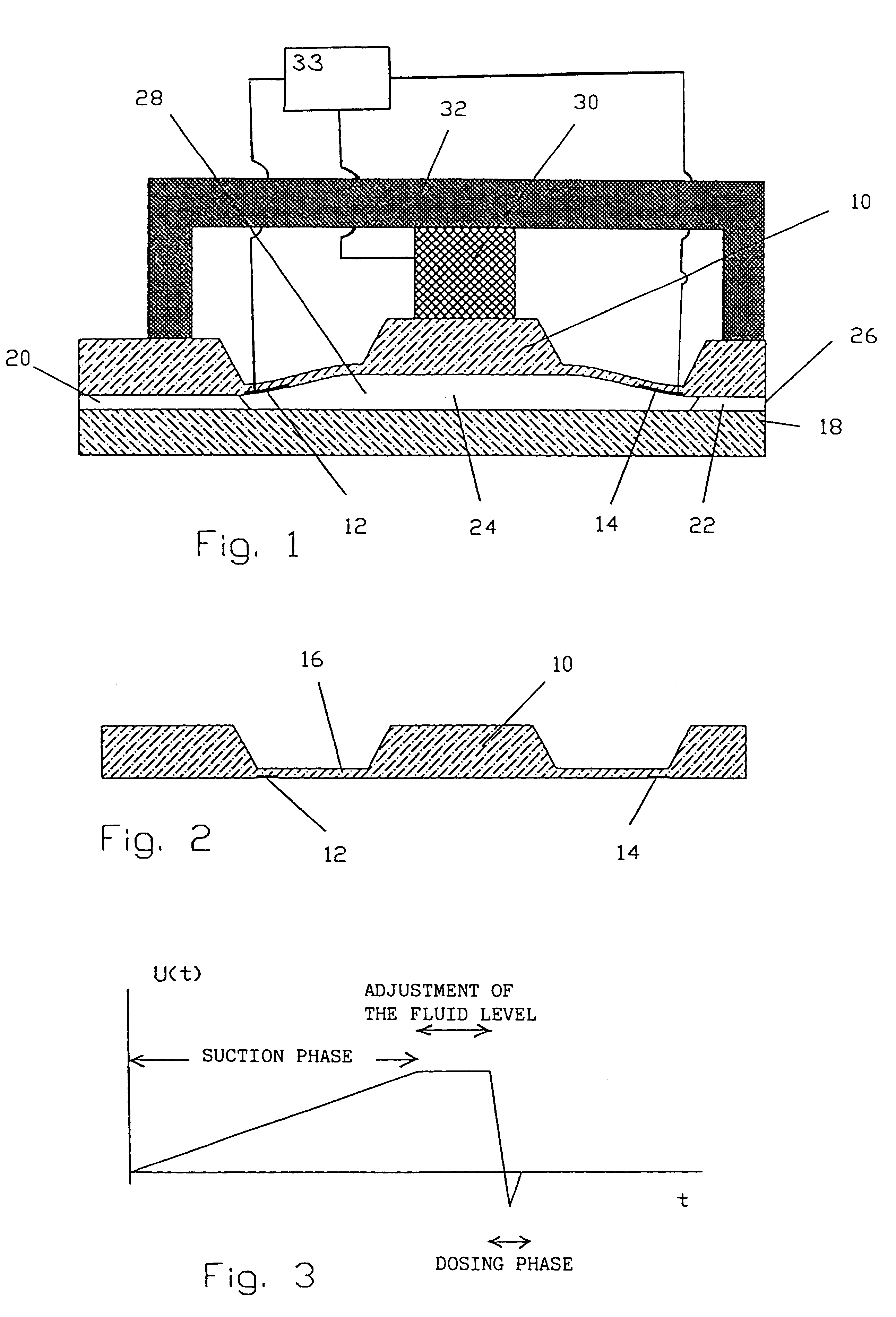
FIG. 1 shows a possible embodiment of the microdosing device according to the present invention, which is particularly suitable for producing the dosing element by means of semiconductor-technological methods. In the embodiment shown the media displacer 10 is realized as a stiffened membrane which is etched in silicon. In this embodiment, the volume sensor consists of piezoresistive resistors 12 and 14 which are integrated in the media displacer. The mechanical stress resulting from a specific displacer position at the location of the resistors 12 and 14 in the media displacer 10 is converting into an electric signal via the piezoresistive effect. Thus, the resistors 12 and 14 represent means for detecting the position of the displacer.

FIG. 2 shows an enlarged cross-sectional view of the displacer structure 10. The displacer structure shown in FIG. 2 is produced by means of anisotropic KOH etching resulting in the trapezoidal recesses which define the membrane 16.

In the embodiment o...


PUM


Abstract

A microdosing device comprises a pressure chamber which is at least partly delimited by a displacer, an actuating device for actuating the displacer, the volume of the pressure chamber being adapted to be changed by actuating the displacer, a media reservoir which is in fluid comunication with the pressure chamber via a first fluid line, and an outlet opening which is in fluid communication with the pressure chamber via a second fluid line. The microdosing device additionally comprises a means for detecting the respective position of the displacer and a control means which is connected to the actuating device and to the means for detecting the position of the displacer, said control means controlling the actuating device on the basis of the detected position of the displacer or on the basis of displacer positions detected during at least one preceding dosing cycle so as to cause the discharge of a defined volume of fluid from the outlet opening. The control means comprises means for controlling the actuating device with a signal of low edge steepness so as to cause the displacer to move from a first position to a predetermined second position, the second position of the displacer defining a larger volume of the pressure chamber than the first position. In addition, the control means comprises means for controlling the actuating device with a signal of high edge steepness so as to cause the displacer to move from the second position to the first position for discharging in this way a defined volume of fluid from the outlet opening.

Description

1. Field of the InventionThe present invention relates to a microdosing device and to a method for operating the same.2. Description of Prior ArtPrecise dosing of extremely small volumes of liquid in the range between 0.01 .mu.l and 1 .mu.l is of great and decisive importance e.g. in the fields of biotechnology, DNA analytical chemistry and combinatorial chemistry. According to the prior art, dispensers or pipettes are predominantly used for dosing small volumes. The volume to be dosed is in these cases displaced either directly, by a so-called piston-type direct displacement, or via an intermediate air cushion. In this respect, reference is made e.g. to the article "Pipettieren und Dispensieren", A. Jahns, Fachzeit-schrift der Technischen Assistenten in der Medizin, volume 8 (1993), No. 12, pp. 116-1172, Umschau Zeitschriftenverlag.Air-cushion pipettes are suitable for dosing volumes between 0.01 .mu.l and 5 ml, accuracies of .+-.2-3% being achieved when the volumes exceed 1 .mu.l....

Claims


Application Information

Patent Timeline
IPC IPC(8): B01L3/02B01L3/00B05B9/04F04B43/02F04B43/04F04B19/00G01F11/08G01F11/02G01N35/00H01L41/00G01N1/00B05B12/00C40B60/14G01N35/10
CPCH01L41/00B01L3/0265B01L3/0268B05B9/0413F04B19/006F04B43/046G01F11/08G01N35/00G01N2035/00237B01J2219/00364B01J2219/00378B01L3/5027B01L2200/146B01L2300/0816B01L2300/0887B01L2400/0406B01L2400/0439B01L2400/0487C40B60/14F04B2201/0201B01J2219/00351H10N30/00
Inventor ZENGERLE, ROLANDFREYGANG, MICHAELSTEHR, MANFREDMESSNER, STEPHANASHAUER, MATTHIASROSSBERG, RAINER
Owner ZYRUS BET GMBH & CO PATENTE I KG
Why Eureka
Try Eureka