

Non-electrolytic gold plating liquid and non-electrolytic gold plating method using same
a non-electrolytic, gold plating technology, applied in the direction of liquid/solution decomposition chemical coating, solid/suspension decomposition chemical coating, coating, etc., can solve the problems of high substitution rate at the onset of reaction, inconvenient electric gold plating, and use of non-electrolytic gold plating method
Inactive Publication Date: 2001-09-11
LEARONAL JAPAN
View PDF8 Cites 47 Cited by
- Summary
- Abstract
- Description
- Claims
- Application Information
AI Technical Summary
Benefits of technology
Another object of the present invention is to provide a method for non-electrolytic gold plating which provides an improved adherence between a base metal surface and a gold-plated layer.
(3) an anti-gold deposit agent which inhibits excess local etching or corrosion by substitution reaction between said metal surface and gold during the gold plating.
Problems solved by technology
Therefore, electric gold plating is not suitable and non-electrolytic gold plating method has to be used.
Currently available substitution gold plating liquids are unable to control the rate of substitution reaction, as a result, the substitution rate is very high at the onset of reaction.
Especially, many defect spots on the substituted gold layer are produced right after the reaction due to that fast substitution reaction, causing continuous defect spots or localized defect area.
Etching or corrosion on the base metal under the defect gold plating layer progresses vertically deep or horizontally wide excessively.
Accordingly, it is known that in the case where gold plating is carried out by use of the currently available substitution gold plating liquid, deep crevasse-like etching along the grain boundary or wide horizontal corrosion develops excessively in the base metal after the gold plating layer is formed.
For example, when general non-electrolytic nickel or gold plating is carried out using the known non-electrolytic nickel plating bath or substitution gold plating bath, scanning electron microscopic examination of a slice of substitution gold layer of 0.05 to 0.1 .mu.m thickness on non-electrolytically plated nickel layer of 0.5 .mu.m revealed that the gold plating liquid preferentially attacked the deposited grain boundary portion of the non-electrolytically formed nickel layer, causing deep corrosion at the grain boundary, resulting in the formation of a cavity under the gold layer.
Such weakening of the non-electrolytically plated nickel layer after the substitution gold plating and unsatisfactory adherence between the gold layer and nickel layer makes the resultant product unendurable to soldering and hence impractical.
Accordingly, in the case of the autocatalytic type gold plating, it is not possible to prevent etching and corrosion of the base metal caused by gold plating liquid.
Such a plated layer with insufficient adherence is prone to peel off during efficacy tests or is unable to provide strength for soldering, resulting in exposure of the base metal after soldering and during soldering strength tests.
However, there is a big problem on production of defect products due to inadequate soldering strength in the currently available non-electrolytic gold plating technology.
If the concentration of a gold ion is lower than 0.1 g / L, the plating reaction becomes very slow or difficult to start.
On the other hand, if the concentration of a gold ion becomes higher than 10 g / L, only little favorable effects can be realized and hence uneconomical.
When the concentration of the complexation agent is less than 0.005 mole / L, the agent is apt to be incapable of maintaining a gold ion in the liquid, and consequently gold is prone to precipitate from the plating liquid.
On the other hand, the concentration of the complexation agent is higher 0.5 mole / L, only little improvement is realized and hence uneconomical.
On the other hand, the concentration of the anti-gold deposit agent is more than 100 g / L, only little improvement is realized and hence uneconomical.
When the temperature is lower than 50.degree. C., the rate of formation of plating layer tends to become too slow and lower productivity and thus uneconomical, while the temperature is higher than 95.degree. C., the components of the plating liquid may decompose.
Method used
View moreImage
Smart ImageViewing Examples

Examples
example 2
Potassium gold(I) cyanide 2 g / L (as gold ion)
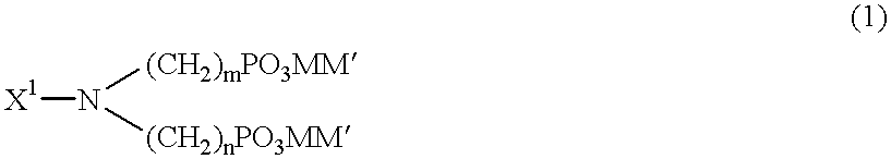
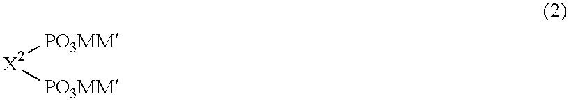
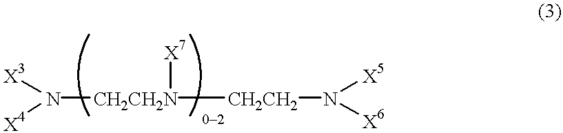
Ethylenediaminetetramethylenephosphonic acid 0.15 mole / L
Reaction product between epichlorohydrin and dimethylaminopropylamine 1 g / L
pH 7.0
example 3
Potassium gold(I) cyanide 2 g / L (as gold ion)
Ethylenediaminetetramethylenephosphonic acid 0.15 mole / L
Imidazole 5 g / L
pH 7.0
example 4
Potassium gold(I) cyanide 2 g / L (as gold ion)
Ethylenediaminetetramethylenephosphonic acid 0.15 mole / L
Reaction product between epichlorohydrin and imidazole 1 g / L
pH 7.0
Login to View More PUM
| Property | Measurement | Unit |
|---|---|---|
| Concentration | aaaaa | aaaaa |
| Concentration | aaaaa | aaaaa |
| Concentration | aaaaa | aaaaa |
Abstract
The present invention provides an excellent non-electrolytic gold plating liquid which produces a gold plating layer firmly adhered to a surface selected from the group consisting of nickel, cobalt, palladium or a metal alloy containing nickel, cobalt or palladium, as well as a method for performing a non-electrolytic gold plating method using the non-electrolytic gold plating liquid. The non-electrolytic gold plating liquid comprises:(1) a water-soluble gold compound;(2) a complexation agent which stabilizes a gold ion in the plating liquid, but does not substantially dissolve nickel, cobalt or palladium; and(3) an anti-gold deposit agent which inhibits excess local etching or corrosion by substitution reaction between the metal surface and gold during the gold plating.
Description
The present invention relates to a non-electrolytic gold plating liquid and non-electrolytic gold plating method using the non-electrolytic gold plating liquid to form a gold plating layer for electronic industrial parts or articles, such as a print wiring base board and ITO base board, etc. Further, the present invention provides excellent adherence between the base metal and gold layer by inhibition of a local and excess etching or corrosion of metal to be gold plated (or prevent extension of the depth or horizontal etching or corrosion of the subject metal surface). The present invention makes it possible to achieve strong soldering strength between the base metal and the gold plated metal prepared thereon by using the non-electrolytic gold plating liquid. Thus, the present invention relates to a non-electrolytic gold plating liquid, and a method for gold plating using such a non-electrolytic gold plating liquid.TECHNICAL BACKGROUND OF THE INVENTIONGold plating has been applied t...
Claims
Login to View More Application Information
Patent Timeline
 IPC IPC(8): C23C18/31C23C18/42
CPCC23C18/42
InventorOTA, YASUOTAKIZAWA, YASUSHIENOMOTO, HARUKI
OwnerLEARONAL JAPAN