Motorized focusing device and viewing system utilizing same

a focusing device and motorized technology, applied in the field of optical devices, can solve the problems that the manual focusing coupler is not adapted for use with the auto focusing control, and achieve the effects of convenient use, fast and easy insertion, and simple construction

Inactive Publication Date: 2001-09-18
VISTA MEDICAL TECH +1
View PDF12 Cites 62 Cited by
  • Summary
  • Abstract
  • Description
  • Claims
  • Application Information

AI Technical Summary

Benefits of technology

Another object of the present invention to provide an improved endoscope focusing coupler which is (i) simple in construction; (ii) easy to use; (iii) capable of sensitive adjustment; and (iv) readily sterilizable by any of the common and widely available sterilization modalities, such as steam autoclaving, immersion in a sterilizing liquid, and gas sterilization.
A further object of the present invention is to provide an endoscope focusing coupler which may be operated by a surgeon without requiring the use of his hands or the diversion of his attention from the surgical procedure being performed and / or the surgical site image provided by the imaging device.
Still another object of the present invention is to provide a novel focusing coupler that can be quickly and easily inserted between, and coupled to, a conventional optical endoscope and a video camera head.
A further object of the present invention is to provide an improved endoscope / video camera system that utilizes a motorized optical focusing device for sharply focusing images from a conventional optical endoscope onto the imaging plane of a video camera.
Yet another object of the present invention is to provide a motorized focusing coupler for use between a conventional optical endoscope and a video camera head for maintaining the focus of the image presented to the video camera as the object distance is varied.

Problems solved by technology

Also, such manually focused devices require the use of a surgeon's hand, which in turn may require the surgeon to divert his attention from the surgical procedure being performed and / or the video display of the surgical site.
Further, manually operable focusing couplers are not adapted for use with autofocusing controls.

Method used


Image

  • Motorized focusing device and viewing system utilizing same
  • Motorized focusing device and viewing system utilizing same
  • Motorized focusing device and viewing system utilizing same

Examples


Embodiment Construction

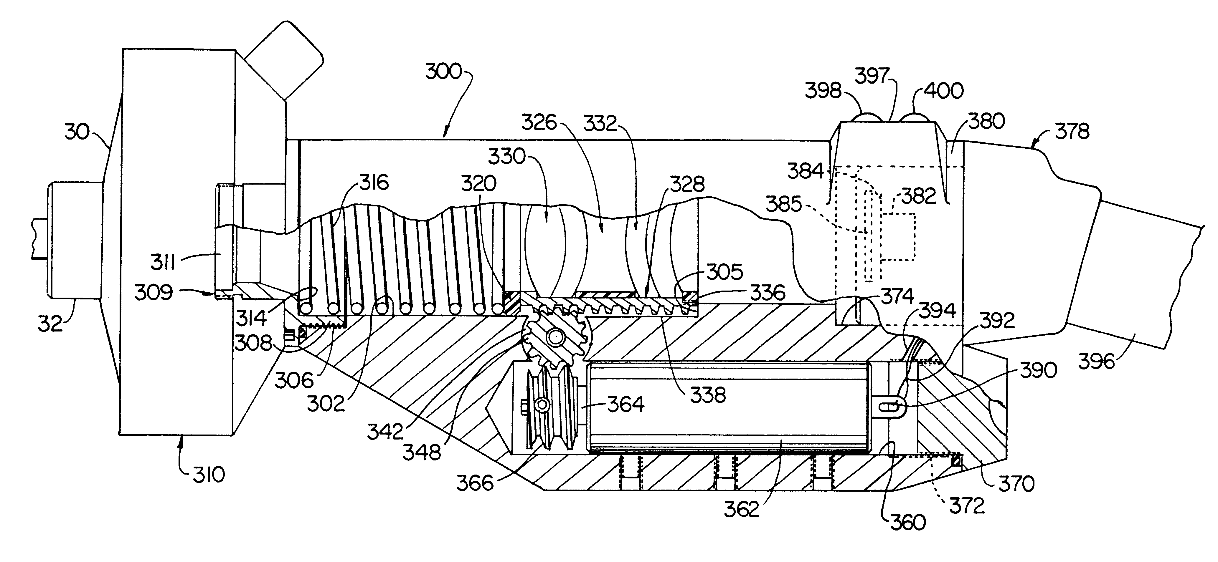
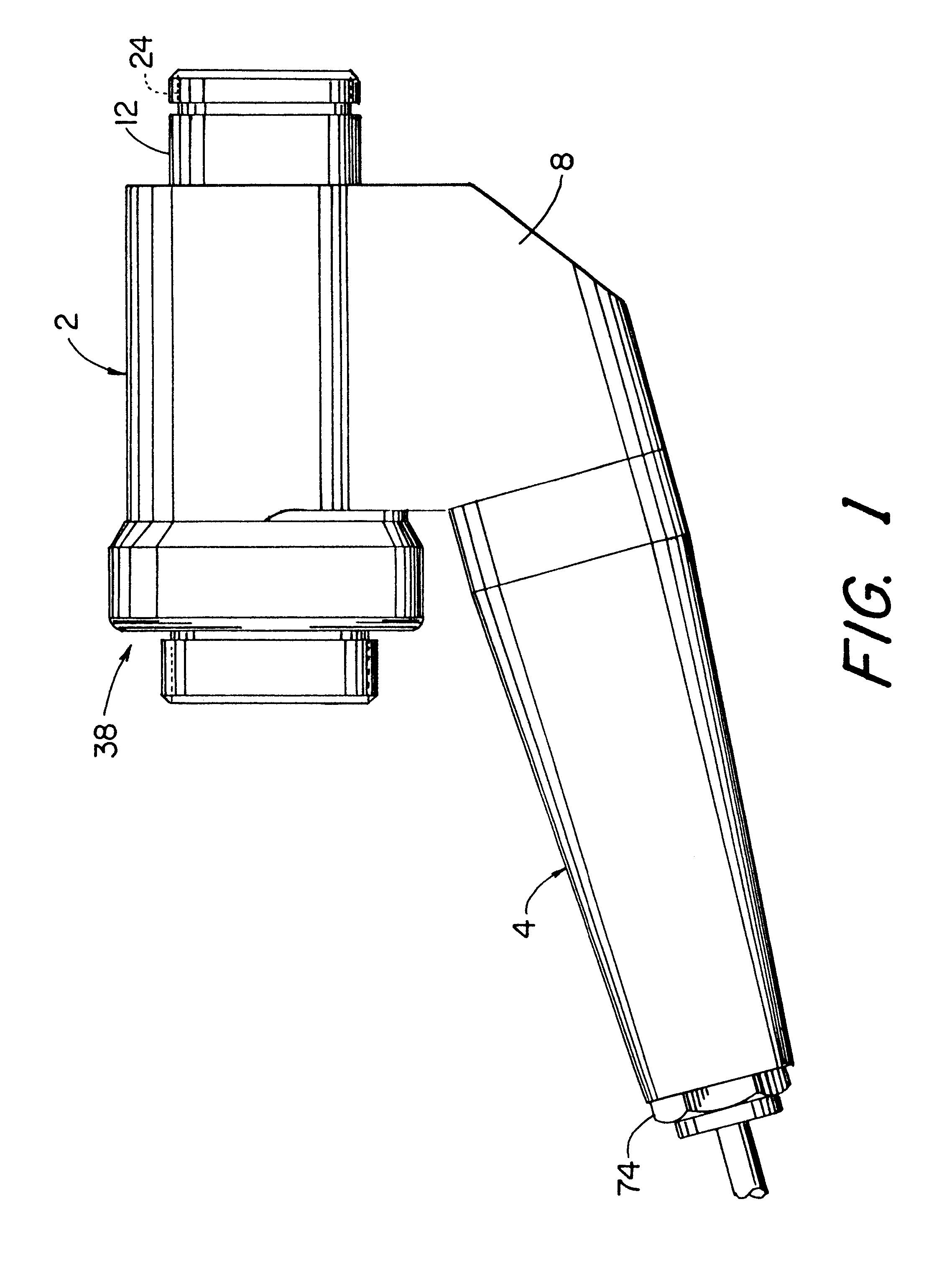
Referring now to the appended drawings, and particularly to FIGS. 1-5, there is shown a preferred embodiment of the motorized focusing coupler of the present invention. This coupler is designed for insertion into an optical path extending between a conventional optical endoscope and an imaging device in the form of a video camera head, as discussed hereinafter in greater detail.

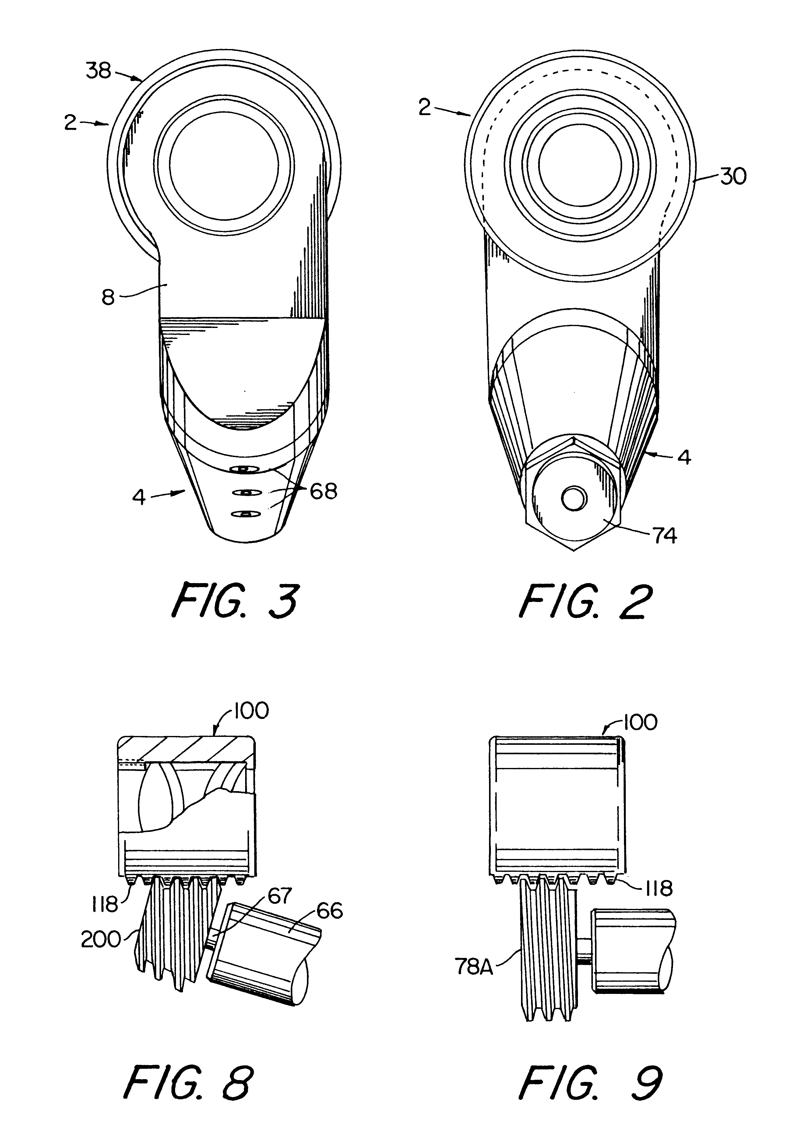
As seen best in FIGS. 1, 4 and 7, the coupler comprises a housing assembly in the form of a main housing 2 and a motor support housing 4. Main housing 2 is formed with a lateral extension 8 to which motor support housing 4 is attached, and also with a cylindrical bore 10 of substantially constant diameter. Housing 2 also has a hollow cylindrical extension 12 (FIG. 4) at its distal end which is coaxial with bore I0. The inner diameter of the distal end of bore 10 is reduced in diameter, thereby forming an annular proximally-facing shoulder 14 which functions as a spring stop as described hereinafter.

As seen in...


PUM


Abstract

An improved focusing coupler device for coupling the image capturing portion of an endoscope to a video camera is disclosed. The coupler device includes a housing having an elongate internal chamber defining an optical pathway for connecting the optical image paths of the endoscope and the camera, first and second windows closing off the opposite ends of the chamber, a lens transport assembly disposed in the chamber for relative movement between the ends of the chamber, the lens transport assembly comprising a lens carrier that defines a longitudinal series of rack gear teeth and is movable between the opposite ends of the chamber, and at least one focusing lens mounted to the lens carrier in coaxial alignment with the longitudinal axis of the chamber. The housing also includes a cavity containing a drive device and a passageway communicating with the midsection of the chamber and the distal end of the cavity chamber, and gear means for connecting the rack gear teeth to the drive device so as to translate rotational movement of the drive shaft in the cavity through the passageway to the rack gear teeth and thereby to selectively longitudinally move the lens transport assembly in the chamber.

Description

1. Field of InventionThe present invention generally relates to optical devices wherein one or more movable lenses are provided for focusing an image of an object in a preselected plane. More particularly, the invention relates to an improved focusing coupler capable of varying the field of view and magnification, and to a viewing system utilizing the same, for use by surgeons in endoscopically viewing internal, "closed", surgical sites.2. Summary of the Prior ArtEndoscopes are medical devices which are used to provide external images of organs and structures within a human or animal. As used herein, the term "endoscope" includes, but is not limited to, arthroscopes, colonoscopes, bronchoscopes, hysteroscopes, cystoscopes, sigmoidoscopes, laparoscopes and urethrascopes.Typically, endoscopes comprise an insertion portion in the form of a hollow shaft that is designed for insertion through a body orifice or a small incision into an internal body cavity. An objective lens unit consisti...

Claims


Application Information

Patent Timeline
Patent Type & Authority Patents(United States)
IPC IPC(8): G02B23/24G02B7/08A61B1/00
CPCG02B23/2484G02B23/2453G02B7/08A61B1/00188
Inventor LICHTMAN, PHILIP R.
Owner VISTA MEDICAL TECH
Why Eureka
Try Eureka