

Hybrid fiber-reinforced plastic
a technology of fiber reinforced plastics and hybrid fibers, applied in the field of hybrid fiber reinforced plastics, can solve the problems of inability to fully manifest the outstanding characteristics the danger of failure of carbon fiber reinforced plastics, and the application restriction, so as to prevent the overall failure of the member, facilitate the manufacture, and prevent the effect of splitting
- Summary
- Abstract
- Description
- Claims
- Application Information
AI Technical Summary
Benefits of technology
Problems solved by technology
Method used
Image

Examples
example 2
PAN-based carbon fibre bundles and nylon 66 fibre bundles identical to those used in Example 1 were uni-directionally aligned and laid out in the form of a sheet. The pitch between the nylon 66 fibre bundles at this time was made 15 mm. Hybrid prepreg C (prepreg weight per unit area 311 g / m.sup.2, fibre content 68 wt %) was prepared by impregnating this with B-stage epoxy resin. The percentage by volume of the nylon 66 fibre in terms of the carbon fibre in hybrid prepreg C was 10%.
A shaft for a ski pole was produced in the same way as in Example 1 except that there was used hybrid prepreg C instead of hybrid prepreg B.
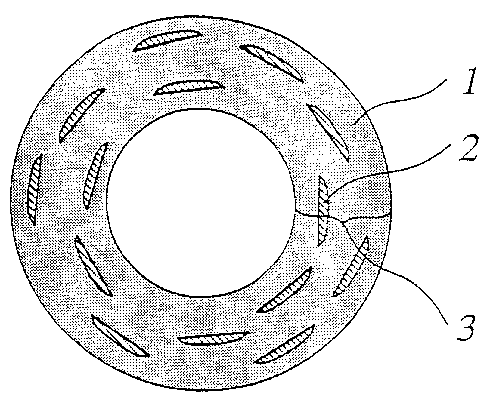
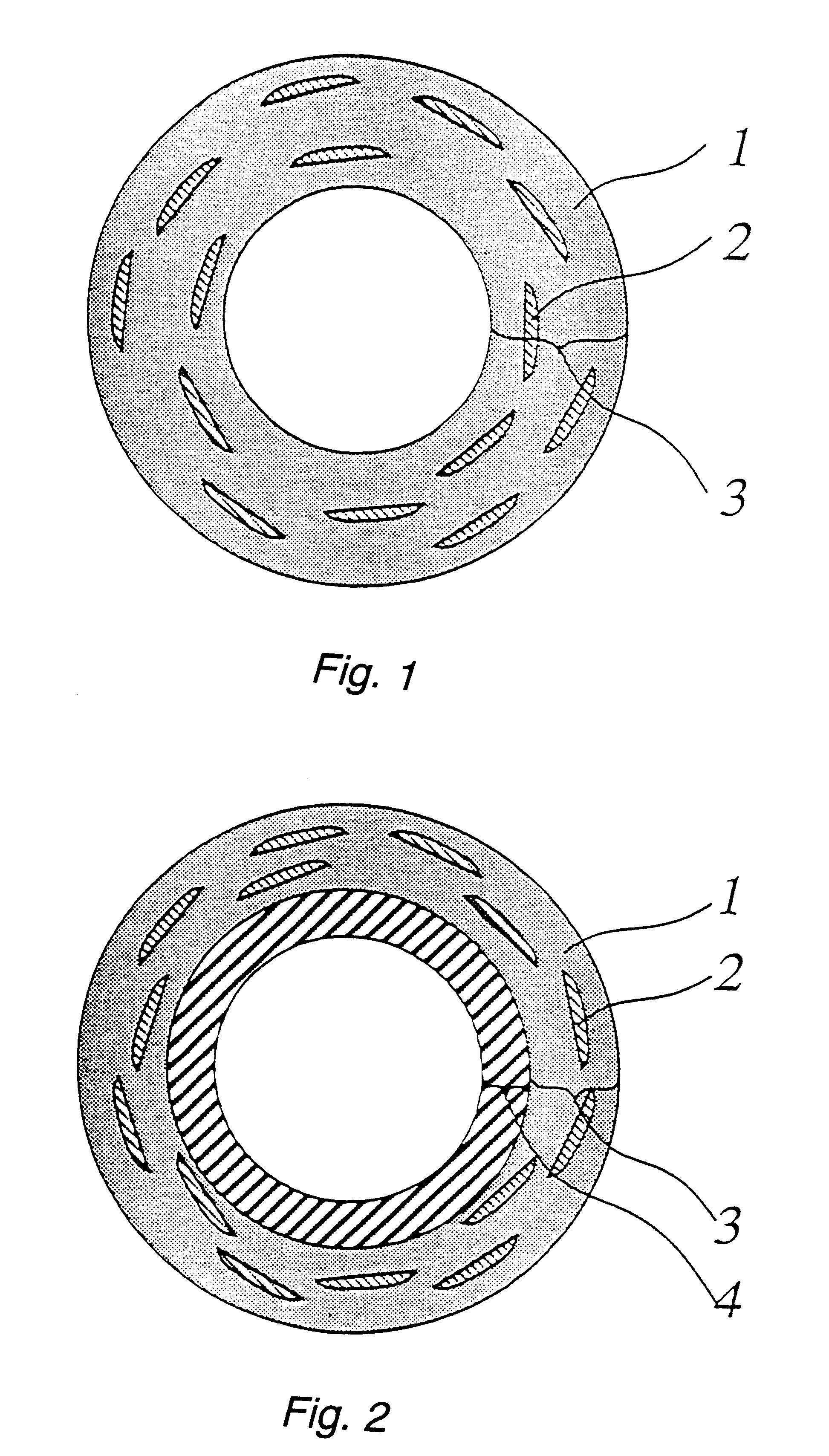
When the end faces of this shaft were polished and observed with an optical microscope, it was seen that the hybrid region on the shaft exterior where the fibre direction was parallel to the principal axis had a sea / islands structure in which regions having nylon 66 fibre were dispersed in the region having carbon fibre. The wall thickness of the shaft was 1.5 mm.
When ...
example 3
PAN -based carbon fibre bundles and nylon 66 fibre bundles identical to those used in Example 1 were uni-directionally aligned and laid out in the form of a sheet. The pitch between the nylon 66 fibre bundles at this time was made 5 mm. Hybrid prepreg D (prepreg weight per unit area 296 g / m.sup.2, fibre content 66 wt %) was prepared by impregnating this with B-stage epoxy resin. The percentage by volume of the nylon 66 fibre in terms of the carbon fibre in this hybrid prepreg D was 29%.
A shaft for a ski pole was produced in the same way as in Example 1 except that there was used hybrid prepreg D instead of hybrid prepreg B.
When the end faces of this shaft were polished and observed with an optical microscope, it was seen that the hybrid region on the shaft exterior where the fibre direction was parallel to the principal axis had a sea / islands structure in which regions having nylon 66 fibre were dispersed in the region having carbon fibre. The wall thickness of the shaft was 1.5 mm....
example 4
PAN-based carbon fibre bundles identical to those used in Example 1 and polyester fibre bundles (number of filaments 360, thickness 167 tex, elongation 11.8%, tensile strength 0.77 N / tex) were uni-directionally aligned and laid out in the form of a sheet. The pitch between the polyester fibre bundles at this time was made 10 mm. Hybrid prepreg E (prepreg weight per unit area 314 g / m.sup.2, fibre content 68 wt %) was prepared by impregnating this with B-stage epoxy resin. The percentage by volume of the polyester fibre in terms of the carbon fibre in this hybrid prepreg E was 10%.
A shaft for a ski pole was produced in the same way as in Example 1 except that there was used hybrid prepreg E instead of hybrid prepreg B.
When the end faces of this shaft were polished and observed with an optical microscope, it was seen that the hybrid region on the shaft exterior where the fibre direction was parallel to the principal axis had a sea / islands structure in which regions having polyester fib...
PUM
| Property | Measurement | Unit |
|---|---|---|
| Linear density | aaaaa | aaaaa |
| Linear density | aaaaa | aaaaa |
| Length | aaaaa | aaaaa |
Abstract
Description
Claims
Application Information