

Resin sheet, process and apparatus for producing same, surface light source element and laminate
a technology of resin sheet and surface light source element, which is applied in the direction of waveguides, lighting and heating apparatus, instruments, etc., can solve the problems of sheet not being sheet is not suitable for light guides, and light divisibility becomes too large, so as to achieve the effect of reducing dust and high ra
- Summary
- Abstract
- Description
- Claims
- Application Information
AI Technical Summary
Benefits of technology
Problems solved by technology
Method used
Image

Examples
example 2
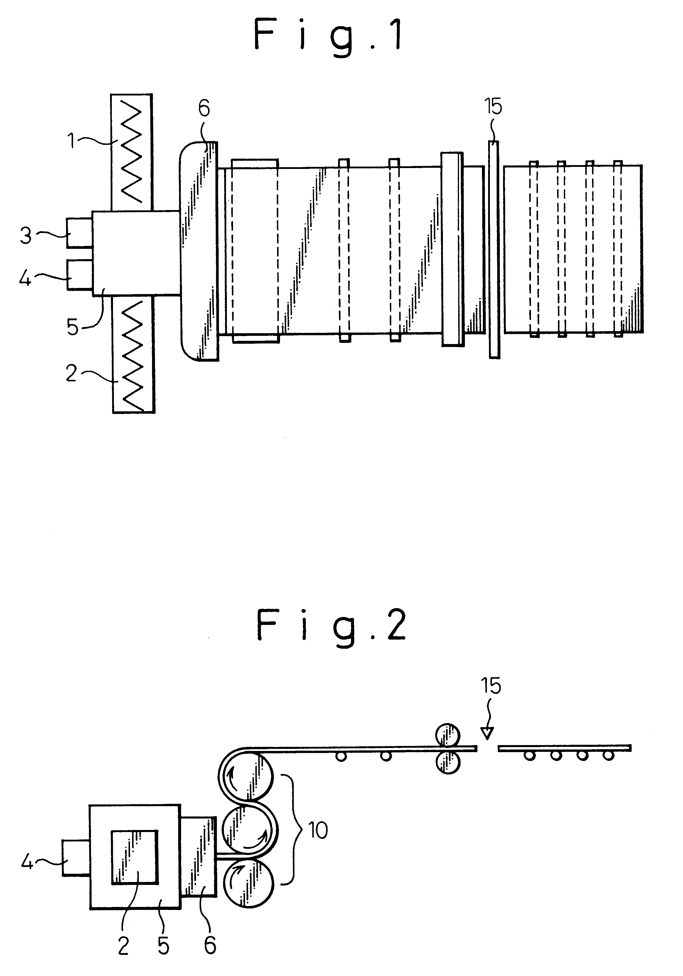
A composite resin sheet having a thickness of 5 mm and a width of 50 cm was continuously molded in the same manner as in Example 1 except that a die 9 having the structure of a composite flow formation portion shown in FIG. 11 was used, and that the height of the flow passages 41 was set at 1 mm.
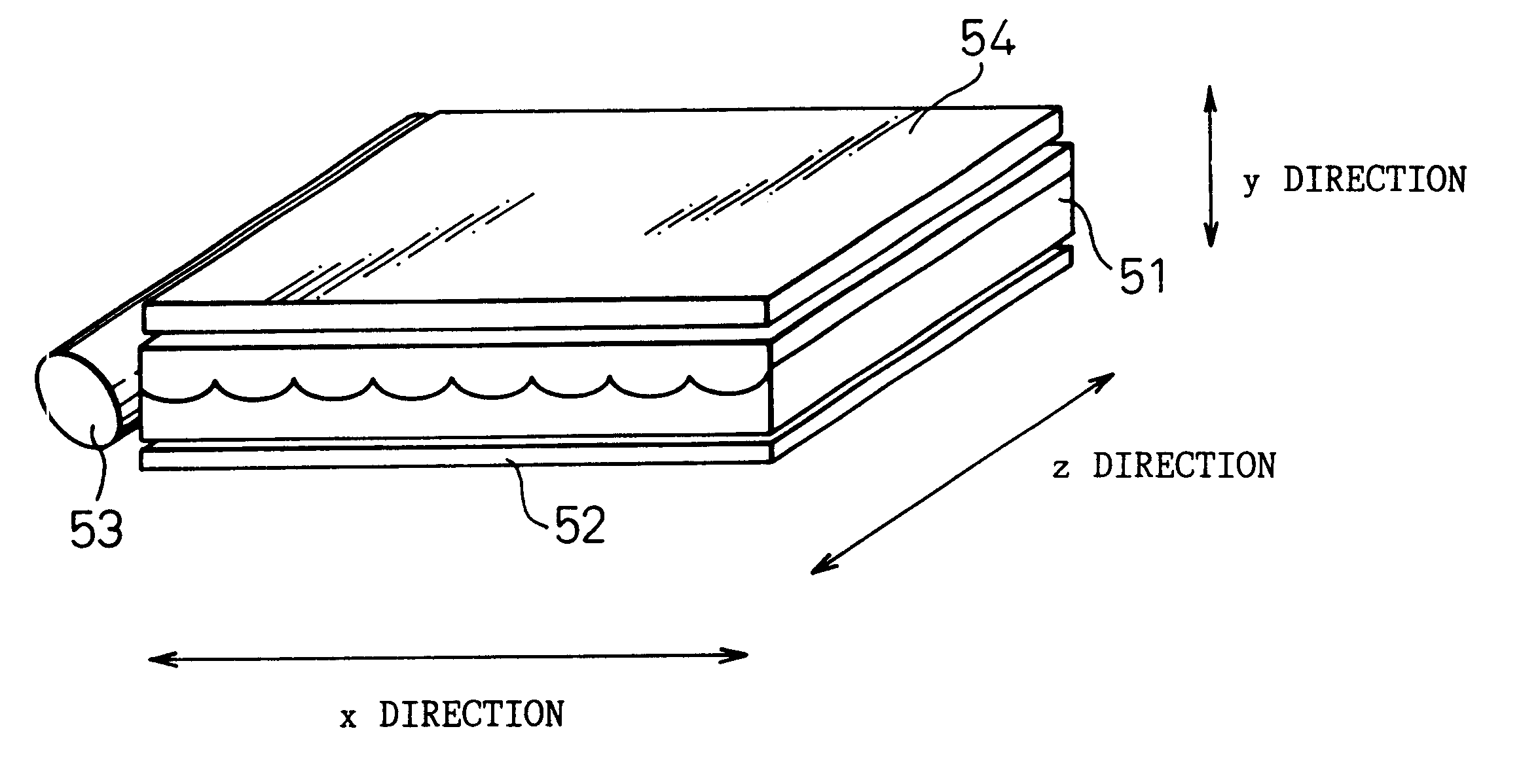
The sheet thus obtained had a smooth surface as a whole, no warpage, and a cross-sectional shape of the resin layer C as shown in FIG. 30d. The depressions and protrusions had a pitch of 5 mm, and an h / p ratio of 0.25. The sheet was excellent in both appearance and light transmittance, showed no uneven light diffusion, and was suited for use in a light illuminator cover and the like.
example 3
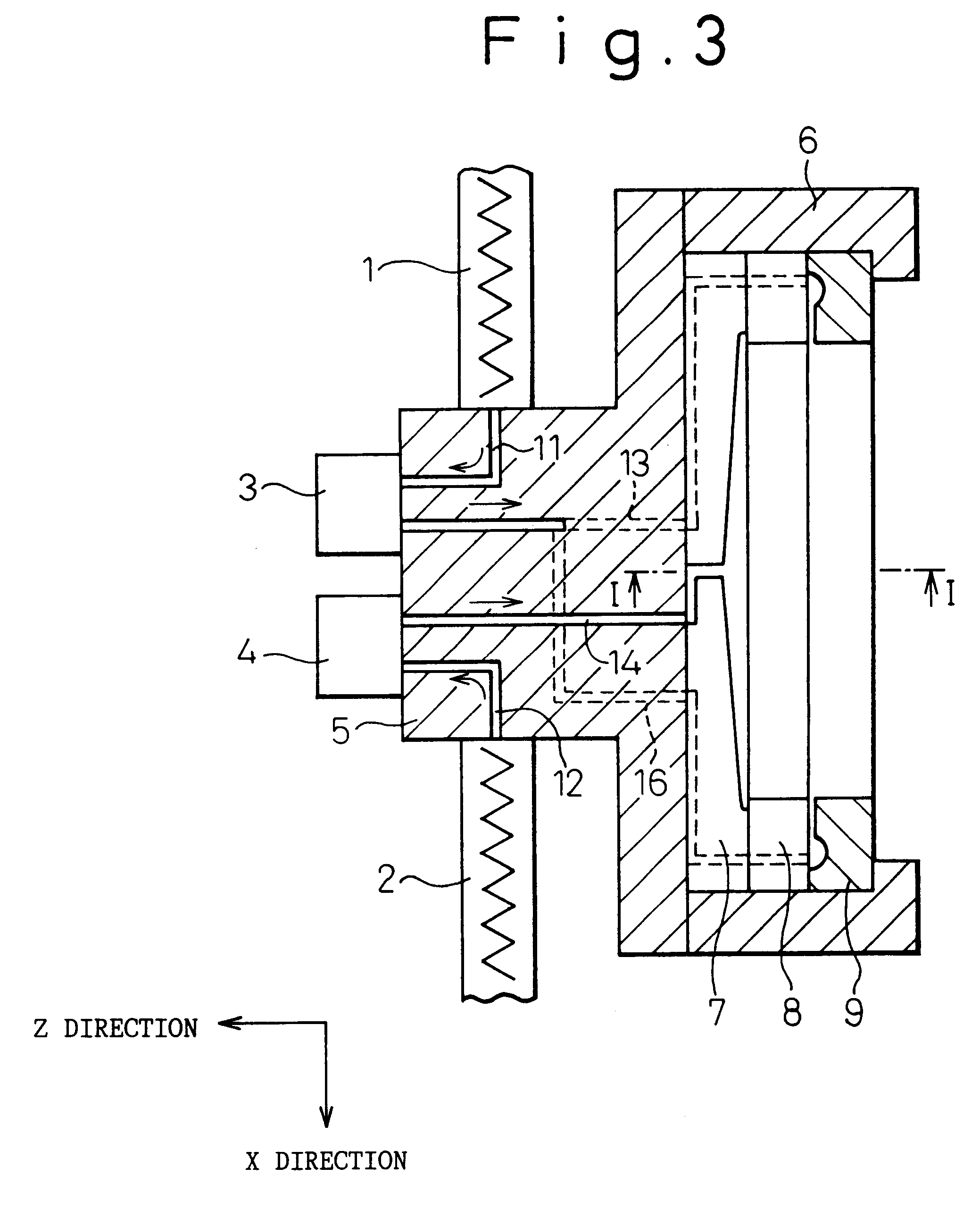
A composite resin sheet having a thickness of 3 mm and a width of 50 cm was continuously molded in the same manner as in Example 1 except in the following respects: the slit gap of the outlet of the flow passage 31 was set at 3 mm; the pitch p of the groove portions of the flow passages 41, 42 was set at 1.5 mm; and the width of the portions Ln and Rn was set at 0.75 mm (P / 2).
The sheet thus obtained had a smooth surface as a whole, no warpage, and the cross-sectional shape of the resin layer C as shown in FIG. 30a. The depressions and protrusions had a pitch of 1.5 mm, and an h / p ratio of 0.25. The sheet was excellent in both appearance and light transmittance, showed no uneven light diffusion, and was suited for use in a light diffusing plate and the like.
example 4
A composite resin sheet having a thickness of 3 mm and a width of 50 cm was continuously molded in the same manner as in Example 1 except that the flow passage set so that it made an angle .PHI. of 60.degree. with the YZ plane.
The sheet thus obtained had a smooth surface as a whole, no warpage, and the cross-sectional shape of the resin layer C as shown in FIG. 30c. The depressions and protrusions had a pitch of 5 mm, and an h / p ratio of 0.25. The sheet was excellent in both appearance and light transmittance.
PUM
| Property | Measurement | Unit |
|---|---|---|
| Size | aaaaa | aaaaa |
| Size | aaaaa | aaaaa |
| Fraction | aaaaa | aaaaa |
Abstract
Description
Claims
Application Information