

Piston for internal combustion engines
a technology for internal combustion engines and pistons, which is applied in the direction of machines/engines, pressure lubrication, mechanical equipment, etc., can solve the problems of excessive temperature of the cross-sectionally angular portion (edge portion) and high thermal load, and achieve the effect of reducing the number of cylinders, and reducing the number of pistons
Inactive Publication Date: 2001-11-13
KOMATSU LTD
View PDF7 Cites 82 Cited by
- Summary
- Abstract
- Description
- Claims
- Application Information
AI Technical Summary
Benefits of technology
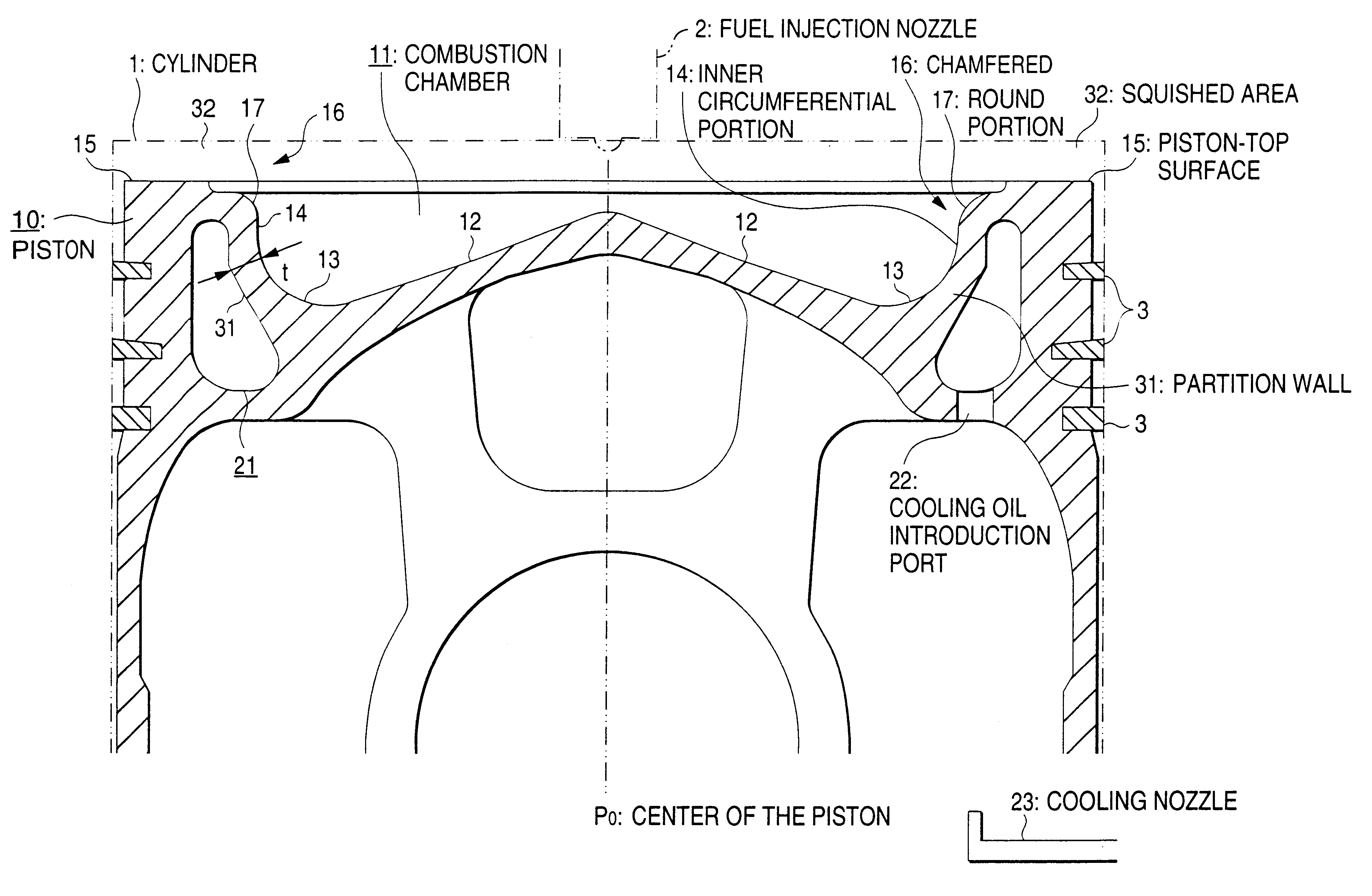
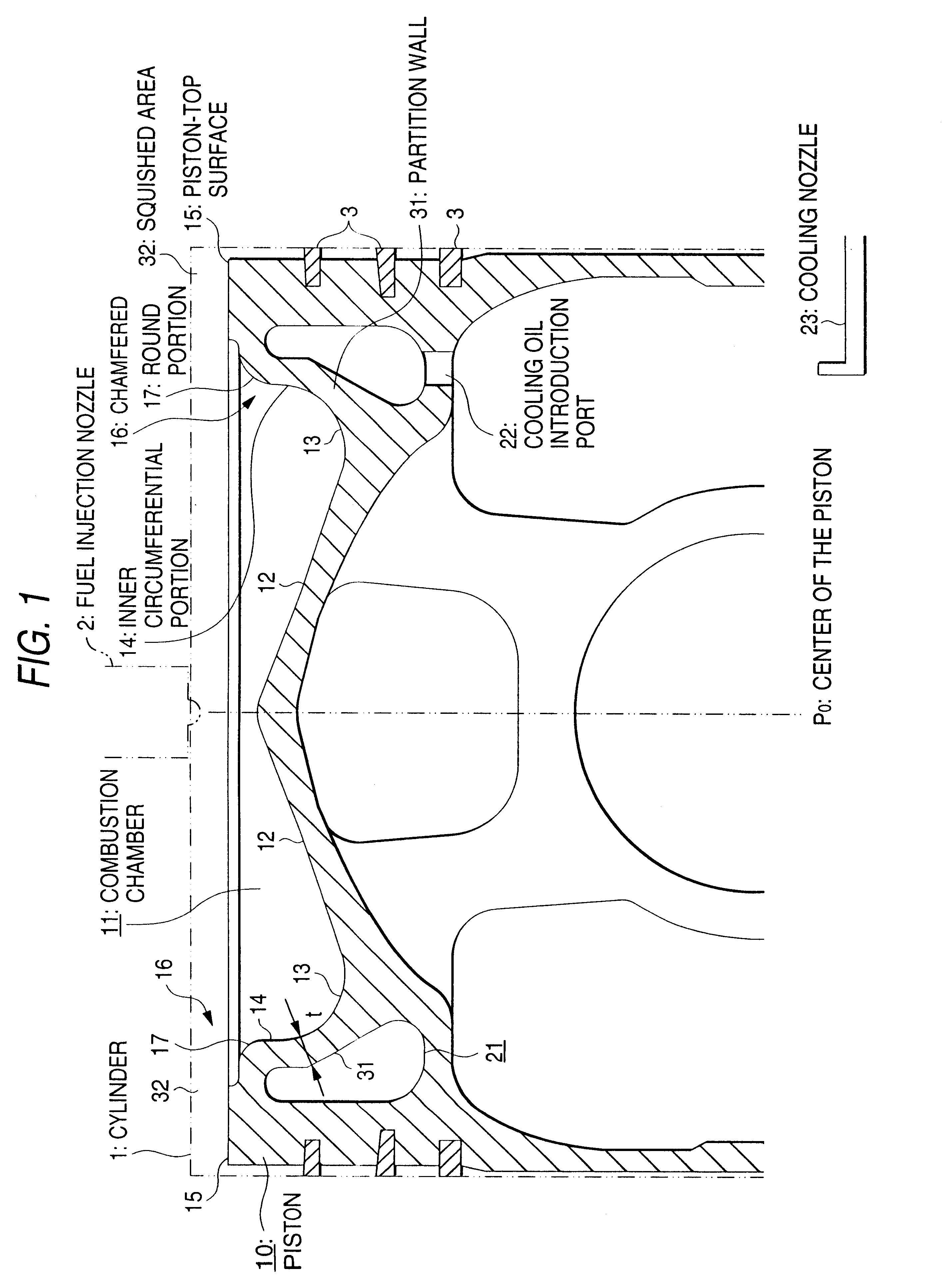
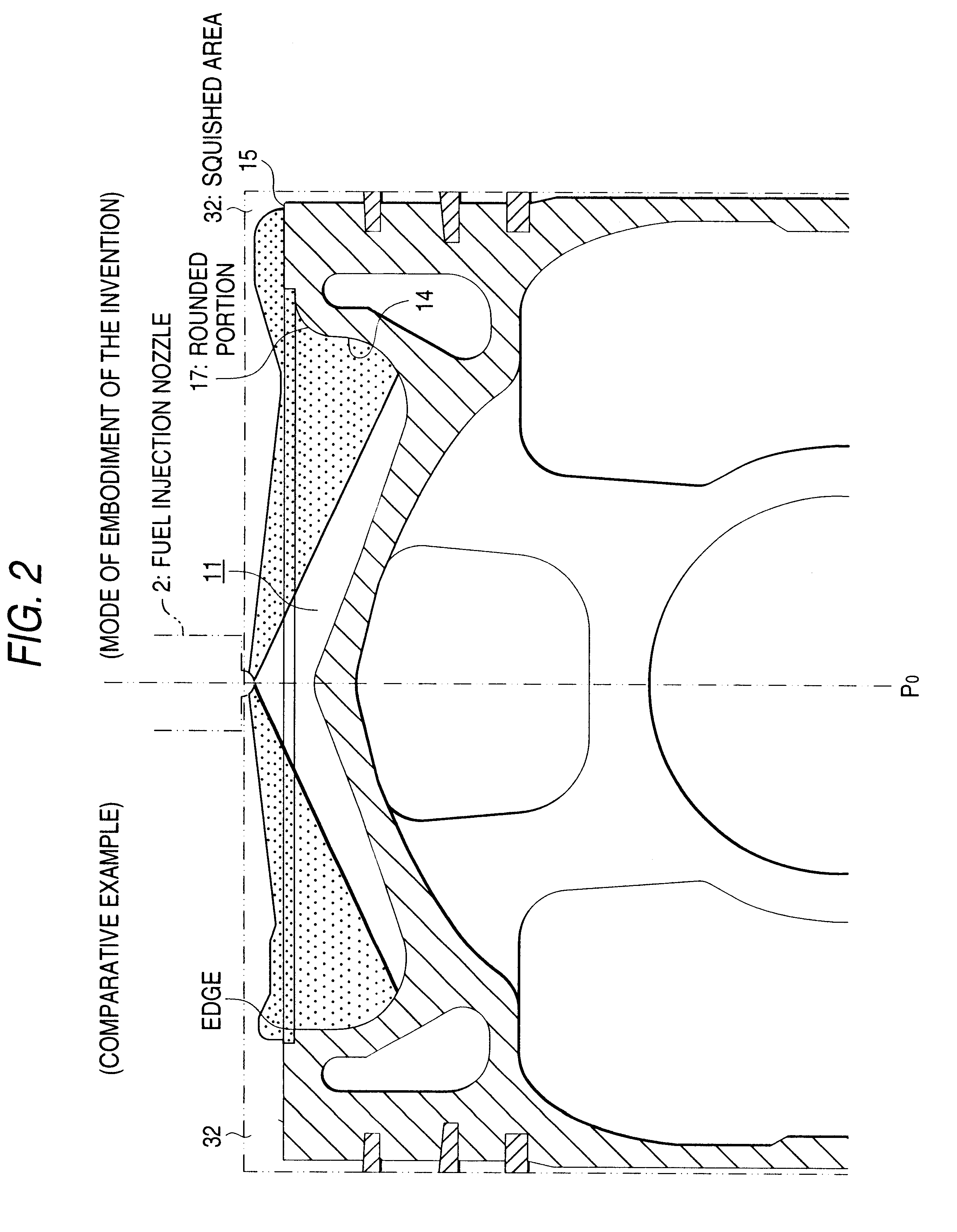
According to this invention, the cross-sectionally angular portion defined by the upper edge portion, at which the combustion chamber is opened in the cylinder, of the inner circumferential surface of the combustion chamber is chamfered greatly in conformity with the cross-sectional shape of the upper portion of the inner circumferential surface of the cooling cavity to such an extent that the thickness of the upper portion of the inner circumferential wall of the cooling cavity does not greatly vary. Namely, unlike a piston of the related art, the piston according to the present invention does not require to form the combustion chamber by shaving the wall thereof from the inner side of the cross-sectionally angular portion defined by the upper edge portion, at which the combustion chamber is opened in the interior of the cylinder, of the inner circumferential surface of the combustion chamber and the piston-top surface. Therefore, the combustion chamber can be formed easily.
Since the partition wall between the combustion chamber and cooling cavity is formed to a substantially equal thickness, heat points, in which the temperature rises excessively, rarely occur in some regions of these parts. Accordingly, problems ascribed to the occurrence of heat points, i.e. inconveniences including the occurrence of cracks due to a decrease in the high temperature resistance of the material of the piston, the thermal deformation of the piston and the thermal stress put thereon can be prevented, and the durability of the combustion chamber can be improved.
According to this invention, an edge portion does not exist, and thermal stress concentration is minimized, so that stress imparted to a combustion chamber can be further reduced. Moreover, when an upper portion of an inner circumferential surface of a combustion chamber is rounded, a cross-sectional shape of an upper portion of an inner wall of the combustion chamber can be set similar to that of an inner circumferential surface of a cooling cavity, so that the thickness of the inner wall of the combustion chamber can be set more constant.
According to these inventions, the combustion chamber is of a shallow bowl-like toroidal type, so that a fuel injected from a fuel injection nozzle thereinto and flames occurring therein flow into a squished area; i.e., a cross-sectionally angular portion, which is defined by an upper edge portion at which the shallow bowl-like toroidal type combustion chamber is opened in a cylinder of an inner circumferential surface thereof and a piston-top surface, of the combustion chamber is chamfered, so that a fuel and flames which are to flow from the combustion chamber into the squished area are not obstructed thereby, this enabling a combustion efficiency, and furthermore the exhaust characteristics to be improved by effectively utilizing the air in the squished area.
Especially, when after-top-dead-center injection (ATDC), measures employed in a shallow bowl-like toroidal type combustion chamber so as to meet the recent exhaust regulations are taken, i.e., when the fuel is injected under a high pressure from a fuel injection nozzle into the combustion chamber so that the injection finishes in a position in which the piston moves down slightly from a top dead center, or, to be exact, at the time at which a crank angle of around 20 degrees is attained, the atomized and injected fuel and flames can expand smoothly over the chamfered portion into the squished area. Therefore, the air in the squished area can be utilized sufficiently. This enables the exhaust characteristics to be improved.
Problems solved by technology
Such a structure is effective when an engine output is at a normal level but, when the level of an engine output is increased high, a high thermal load is imparted to the piston, so that the temperature of the cross-sectionally angular portion (edge portion) excessively increases.
This would cause inconveniences to occur which include cracks ascribed to a decrease in the high-temperature strength of the material of the piston, the thermal deformation thereof and a high thermal stress put thereon.
Therefore, the durability of the combustion chamber decreases.
Therefore, it is hard to make this piston since it has so to speak a structure obtained by shaving off a circumferential wall thereof from the inner side of the cross-sectionally angular portion (edge portion) thereof.
Therefore, heat points readily occur on the edge, and a sufficiently much improvement of the durability of the piston cannot be expected.
In addition, the difficulty in cooling the opposite portion of the combustion chamber, i.e. the lower portion thereof arises as a new problem.
Therefore, the combustion efficiency is low, and the improving of the exhaust characteristics cannot be expected.
The difference in level is provided not over the whole circumference of the piston but only in the portion thereof which interferes with the valve, and it is not of such dimensions that cause a special problem to arise.
Method used
View moreImage
Smart ImageViewing Examples

Examples
Embodiment Construction
. . . (MODE OF EMBODIMENT OF THE INVENTION), C . . . EDGE. FIG. 3: A . . . BLACK, B . . . COLOR OF EXHAUST GAS (BOSCH INDICATION), C . . . COLORLESS, D . . . 100% LOAD, E . . . (UPPER DEAD CENTER), F . . . INJECTION STARTING TIME (CRANK ANGLE), G . . . 50% LOAD, H . . . 100% LOAD (EDGE), I . . . 50% LOAD (EDGE), J . . . 100% LOAD (LARGE RADIUS), K . . . 50% LOAD (LARGE RADIUS). FIG. 4: Same as the translation of the words shown in FIG. 3.
Login to View More PUM
 Abstract
A piston for internal combustion engines, capable of being manufactured easily and improving the durability of a combustion chamber, moved reciprocatingly in a cylinder of an internal combustion engine, and provided in a top surface thereof with a combustion chamber formed by recessing the same top surface, and in an outer circumferential wall of the combustion chamber with a cooling cavity the inner diameter of a lower portion of an inner circumferential surface of which is set smaller than that of an upper portion thereof, wherein a cross-sectionally angular portion defined by an upper edge portion, at which the combustion chamber is opened in the interior of a cylinder, of an inner circumferential surface of the combustion chamber and a piston-top surface is chamfered greatly in conformity with the cross-sectional shape of the upper portion of the inner circumferential surface of the cooling cavity to such an extent that the thickness of an upper portion of an inner circumferential wall of the cooling cavity does not greatly vary.
Description
1. Field of the InventionThis invention relates to a piston for internal combustion engines, and more particularly to a piston for internal combustion engines which has a combustion chamber in a top surface thereof.2. Description of the Related ArtA piston for internal combustion engines which has a combustion chamber in a top surface thereof, for example, a piston for diesel engines which has a re-entrant type combustion chamber (a combustion chamber having an opened portion of a diameter smaller than a maximum inner diameter of the combustion chamber, and a comparatively deep recess) in a top surface thereof is formed by providing an outer circumferential wall of the combustion chamber with a cooling cavity, into which a cooling oil is injected during an operation of the engine to cool a top portion, the temperature of which becomes high, of the piston, especially, a cross-sectionally angular portion (edge portion) defined by an upper edge of an inner circumferential surface at wh...
Claims
Login to View More Application Information
Patent Timeline
 Patent Type & AuthorityPatents(United States)
IPC IPC(8): F02B23/02F02F3/16F02B23/06F02F3/26F02F3/22F02B3/00F02B3/06F01M1/06
CPCF02B23/0696F02F3/22F02F3/26F02B3/06F02B23/0621F02B23/0651F02B23/0693F02B2275/14F05C2201/021Y02T10/125Y02T10/12
InventorIIJIMA, TADASHIINADA, YORIHIKO
OwnerKOMATSU LTD