Eureka AIR delivers breakthrough ideas for toughest innovation challenges, trusted by R&D personnel around the world.

High efficiency permanent air filter and method of manufacture

a filter and permanent technology, applied in the field of electrostatic filters, can solve the problems of low filtering efficiency, inefficiency of most current inlet air filters for heating and air conditioning systems in capturing small particles, and prior art filters are usually difficult to clean, so as to increase the mechanical particle capturing capacity of the central media, increase the surface area, and improve the effect of corrugation

Inactive Publication Date: 2001-11-27
CHAPMAN RICK L
View PDF16 Cites 58 Cited by
  • Summary
  • Abstract
  • Description
  • Claims
  • Application Information

AI Technical Summary

Benefits of technology

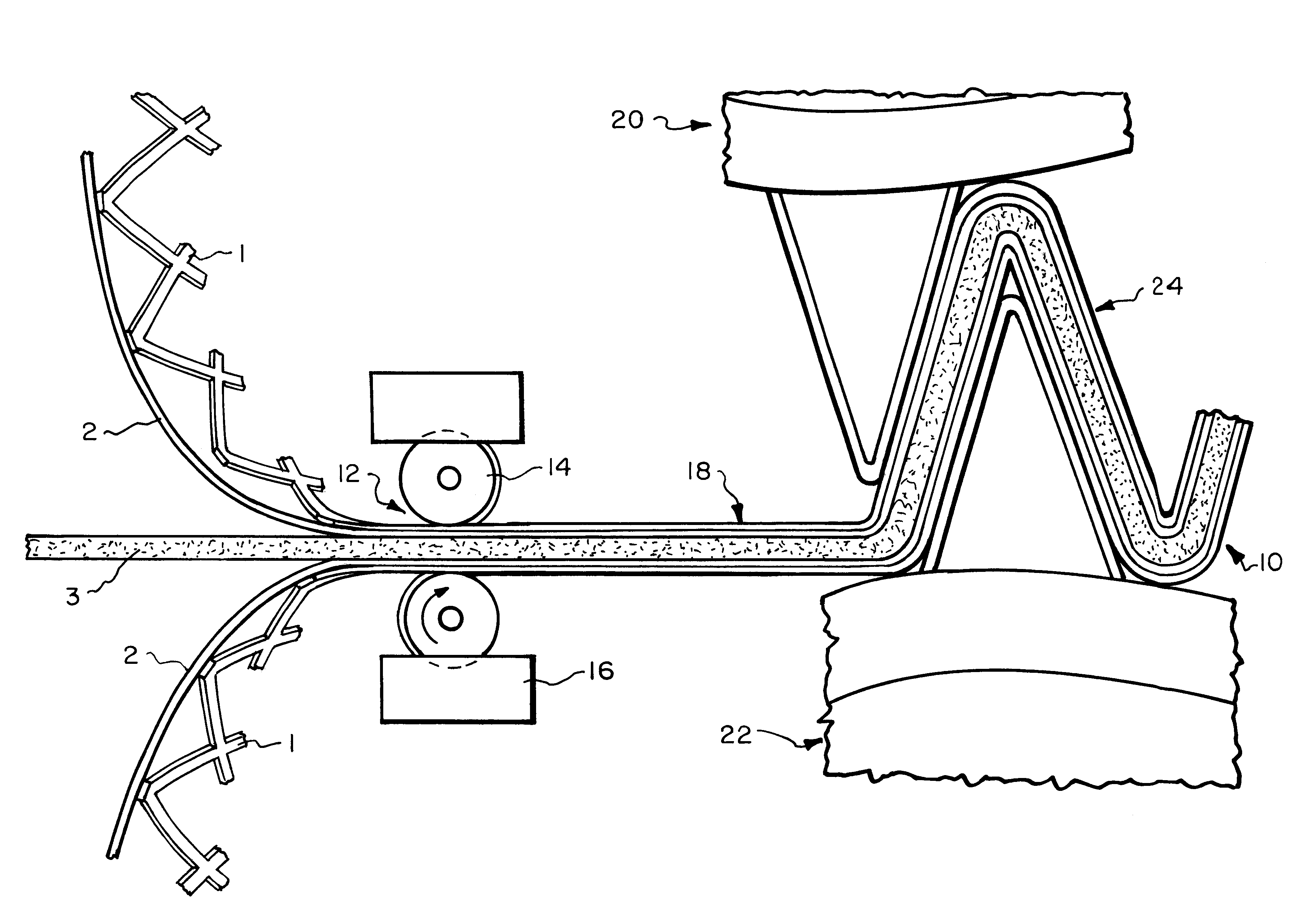
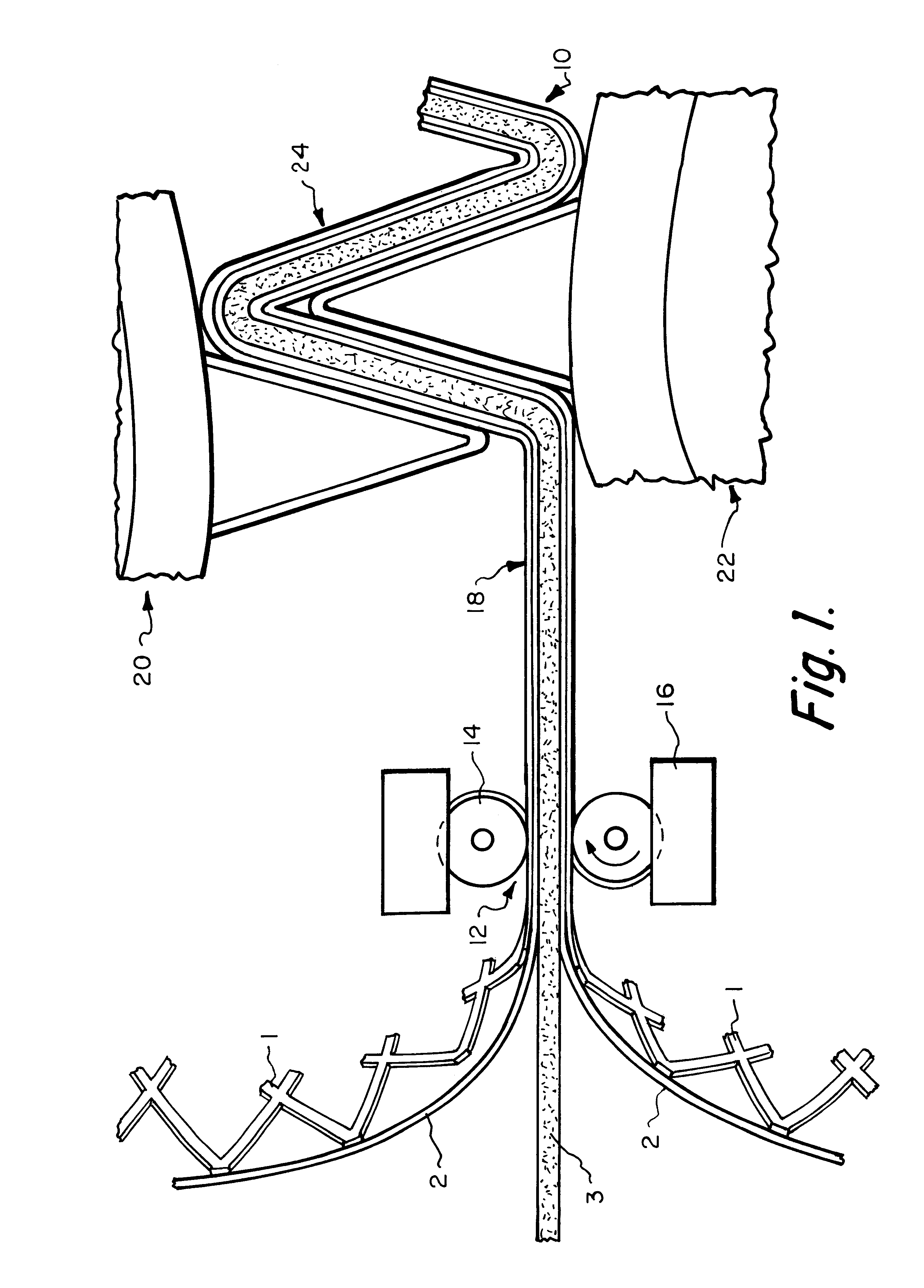
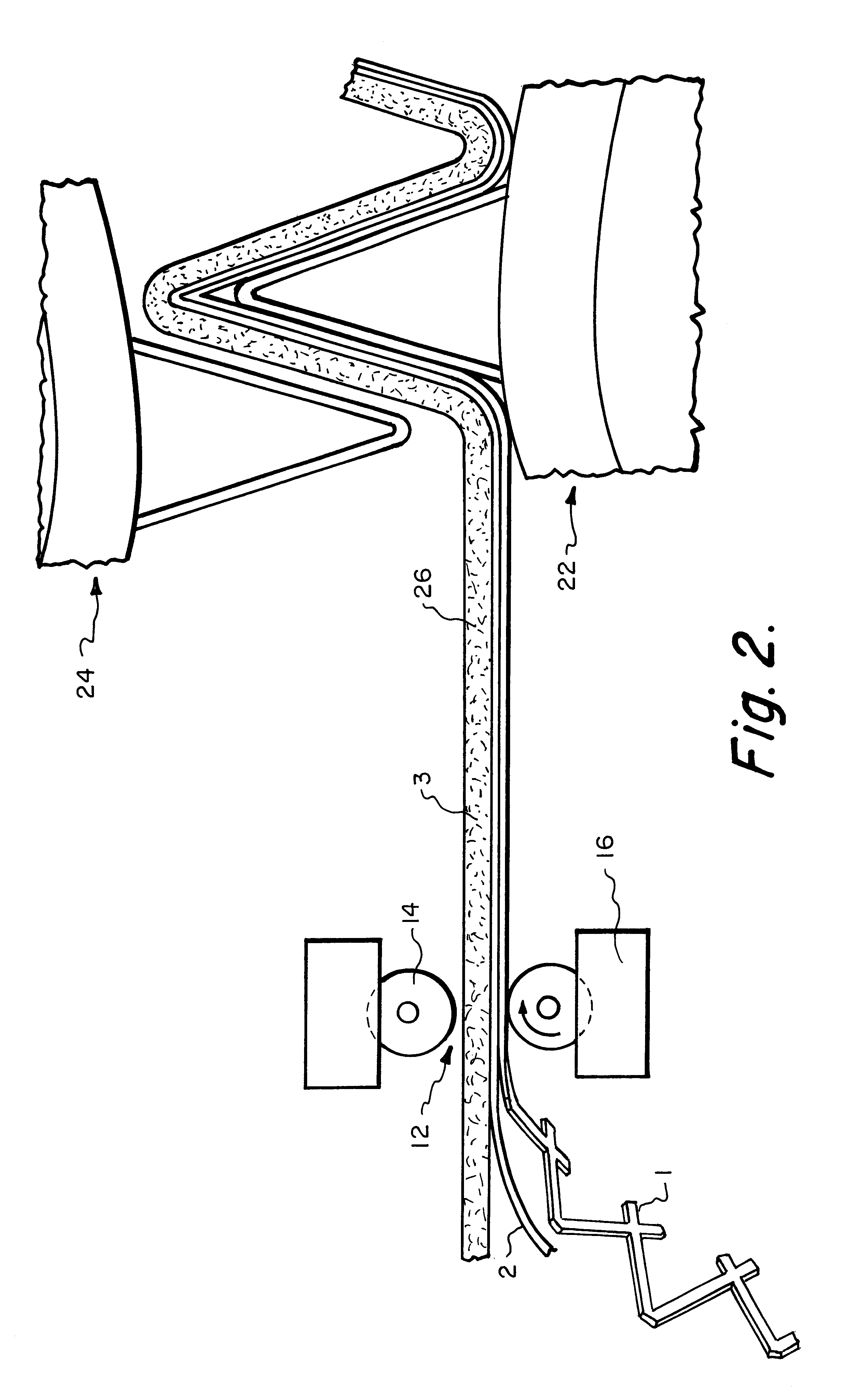
It has been discovered in accordance with this invention that the efficiency of corrugated, electrostatic ventilation filters for small particles can be increased by increasing the mechanical particle capturing capability of the central media. This in combination with increased surface area provided by higher density of corrugations and smaller angles between corrugations provides the desired particle capture efficiency. The porosity of the passive electrostatic netting can be increased to reduce the overall initial resistance of the corrugated media to air flow. Another aspect of the invention relates to the ability to achieve the higher density and lower angle corrugations. In the method of the invention, after leaving the corrugator, the assembly of layers is compressed in a buncher to decrease or increase the width of the corrugations.
The filter of the invention is optimally angled to capture particles. It can be cleaned by vacuuming and / or by washing. The media has low pressure drop and high efficiency for the range of particles experienced with the inlet air. Because it can be cleaned and reused, it can be considered a permanent filter.
The filter media is comprised of fibers of a plastic material such as polyester or nylon held together mechanically by adhesive, thermal bonding or with binder resin, preferably a standard or curable binder resin. The filter media is selected from material which can capture in excess of 80% of particulate matter of 10 micron or less in size. The filter media layer is preferably made from polyester fibers, a curable resin binder preferably containing an antimicrobial agent. The resin can be a curable thermosetting, light cured or water activated resin. The resin may be dispersed throughout the media, applied as stripes to the media at locations corresponding to the tops of the pleats, before or after pleating, preferably after pleating. The resin is then cured to a rigid state to hold the pleats in shape. The rigid filter media, in combination with a passive electrostatic layer can be corrugated without the need of metallic grills to maintain the corrugated shape. The passive electrostatic layer can be a netting material. The electrostatic layer may be made from media such as polypropylene, polyester, nylon or polycarbonate. More preferably, the electrostatic layer is made from DELNET RB0404-12P, a product of Applied Extrusion Technology, Middletown, Del. or equivalent. In use, the air filter would be installed with the electrostatic layer facing upstream. In this embodiment, stitching, stapling, thermal welding, adhesives or other means could be utilized to attach the filter media and electrostatic layer to one another. Additionally, a second electrostatic layer may be disposed on the downstream side of the filter media to increase the filter's efficiency.
The grill may be easily washed. Either side of the grill may face downstream provided the grill layer is the outside layer. It has been discovered that if the grill is positioned between the electrostatic and central layers, adhesive may be used to bond the grill to both layers. This has the advantage of overcoming the resilient tendency of the central layer to become flat. The grill however, may be disposed between the central layer and the netting layer. Testing has shown that while the air flow tends to force the electrostatic layer into the grill and central layer on the upstream side, on the downstream side air flow tends to displace the electrostatic layer away from the central layer. Therefore, it is preferred to position the grill layer as the outside layer on the downstream side.
As the density and thickness of the central filter media is increased, efficiency increased for the same surface area. The efficiency is increased and the resistance decreased by spacing the corrugations closer together such that the angle between the walls of a corrugation are from 0-20% to increase the surface area by at least 90% to about 100%. The pleats per foot increases from about 12 up to about 25.
The resistance to air flow can further be decreased by increasing the porosity of the passive electrostatic netting by at least 10% such as from 1200 cfm frazier to 1300-2000 cfm frazier.

Problems solved by technology

When these filters are first placed in use across an air stream, they have a very low filtering efficiency.
Prior art filters are usually difficult to clean since the dust particles become embedded in the media.
Most current inlet air filters for heating and air conditioning systems are not very efficient in capturing these small particles.
Filters containing layers of electrostatic media perform better within this range of particles but these filters also become clogged.
Since they cannot be efficiently cleaned they must be replaced.
The increased surface area of the novel filter also results in a lower pressure drop than experienced with prior art electrostatic air filters.
These are preferred since the available active electrostatic fibrous materials produce an undesirably high pressure drop as a filtration media and are not cleanable.
If the sheet of material is too thick it is difficult to bend and if it is too thin, it is not capable of holding the multi-layer media in its bent shape.

Method used


Image

  • High efficiency permanent air filter and method of manufacture
  • High efficiency permanent air filter and method of manufacture
  • High efficiency permanent air filter and method of manufacture

Examples


example 2

The central filter media of the filter of Example 1 was replaced with an acrylic bound polyester media formed of 20% of 2.25 denier and 75% of 15 denier polyester fiber blend having a density of 4 ounces per square yard. The corrugations were 12 corrugation per foot. The electrostatic polypropylene netting had a porosity of 1400 cfm and an initial resistance to air flow of 0.14 inches 2.g. The filter was rated at MERV 7.

example 3

The central media of the filter of Example 2 was replaced with a media containing a mixture of 25% 0.9 denier polyester fibers and 75% 3 denier polyester fibers having an overall weight of 2.3 ounces per square yard. The assembly was corrugated to contain 20 corrugations per foot. The initial resistance to air flow was 0.18 inches w.g. and a MERV 8 rating was achieved.

The radial pleat or corrugated air filter has an increased surface area over the prior air flat filter. Its ease of cleaning can be attributed to the filters ability to let the dust collect between the folds and not enter the filter media itself. The filter will have a larger dust holding capacity and will last longer between cleaning. As the filter collects dust, the filter efficiency will increase.

The filter assembly of the invention is suitable for replacement of filters used for filtering incoming air supplied to residential heating and air conditioning systems. The filters usually have a thickness from 0.5 inch to...


PUM

PropertyMeasurementUnit
thicknessaaaaaaaaaa
thicknessaaaaaaaaaa
angleaaaaaaaaaa

Abstract

A novel air filter design for use in residential and commercial heating and air conditioning systems comprising a laminated unit having a filter media where the upstream side of the filter media having a porous layer of passive electrostatic netting. The air filter design has a corrugation configuration to increase the available surface area when compared to conventional flat filters.

Description

TECHNICAL BACKGROUNDThe present invention relates to filters cleanable by washing or vacuuming or the like for inlet air heating and air conditioning systems used in residential or commercial buildings and, more particularly, this invention relates to an electrostatic filter for such systems having an extended service life.Inlet air filters for heating and air conditioning systems have been in use for decades. The inlet air or primary filter was originally intended to protect the heating coils and mechanical devices such as fans from damage by airborne particles. As the harmful effect of inhaled particles on human health became known, inlet air filters were designed remove this particulate matter from the air.The most popular prior art configuration is a thin, rectangular, disposable filter. The filter contains fiberglass, animal hair, fibrous foam or polymeric media or aluminum mesh encased in a cardboard or plastic frame. Prior art filters can comprised polyester panels, urethane ...

Claims


Application Information

Patent Timeline
Patent Type & Authority Patents(United States)
IPC IPC(8): B01D39/16B01D46/52B01D39/08B01D46/00B01D46/10B01D46/12
CPCB01D39/083B01D39/12B01D39/163B01D46/0001B01D46/0032B01D46/0036B01D46/0082B01D46/10B01D46/521B01D2239/0241B01D2239/0435B01D2239/0442B01D2239/065B01D2239/0654B01D2239/0659B01D2239/0668B01D2239/0672B01D2239/0681B01D2239/069B01D2239/086B01D2239/1233B01D2239/1291B01D2275/10B01D2279/50Y10S55/05Y10S264/48B01D46/79
Inventor CHAPMAN, RICK L.
Owner CHAPMAN RICK L
Why Eureka
Eureka Blog
Learn More