Wavelength division multiplexing optical transmission system

a transmission system and optical transmission technology, applied in the field of wavelength division multiplexing optical transmission system, can solve the problems of weak signal light waveform, nonlinear effect, and low wavelength dispersion,

Inactive Publication Date: 2001-11-27
FUJITSU LTD
View PDF1 Cites 48 Cited by
  • Summary
  • Abstract
  • Description
  • Claims
  • Application Information

AI Technical Summary

Problems solved by technology

In this case, as far as the foregoing configuration is concerned, due to wavelength dispersion-slope, it is hard to compensate wavelength dispersion so that wavelength dispersion will become zero relative to all wavelengths.
Consequently, the waveform of signal light is impaired due to interaction between wavelength dispersion that has not been compensated for but cumulated and the nonlinear effect in an optical fiber.
Consequently, the system is susceptible to a nonlinear effect and an optical signal-to-noise ratio becomes low.
Therefore, even when wavelength dispersion and wavelength dispersion-slope are compensated for, a transmission characteristic is not improved satisfactorily.
However, the articles do not refer to the practical characteristics of a dispersion compensation fiber (RDF) used as the second half of the transmission segment of the transmission line.
This hinders alleviation of a nonlinear effect.
Moreover, a transmission loss occurred in the transmission line is approximately 0.225 dB/km.
However, the results of improving a nonlinear effective area and transmission loss are limited.
This results in a large transmission loss and a small nonlinear effective area.
Moreover, ...

Method used


Image

  • Wavelength division multiplexing optical transmission system
  • Wavelength division multiplexing optical transmission system
  • Wavelength division multiplexing optical transmission system

Examples


first embodiment

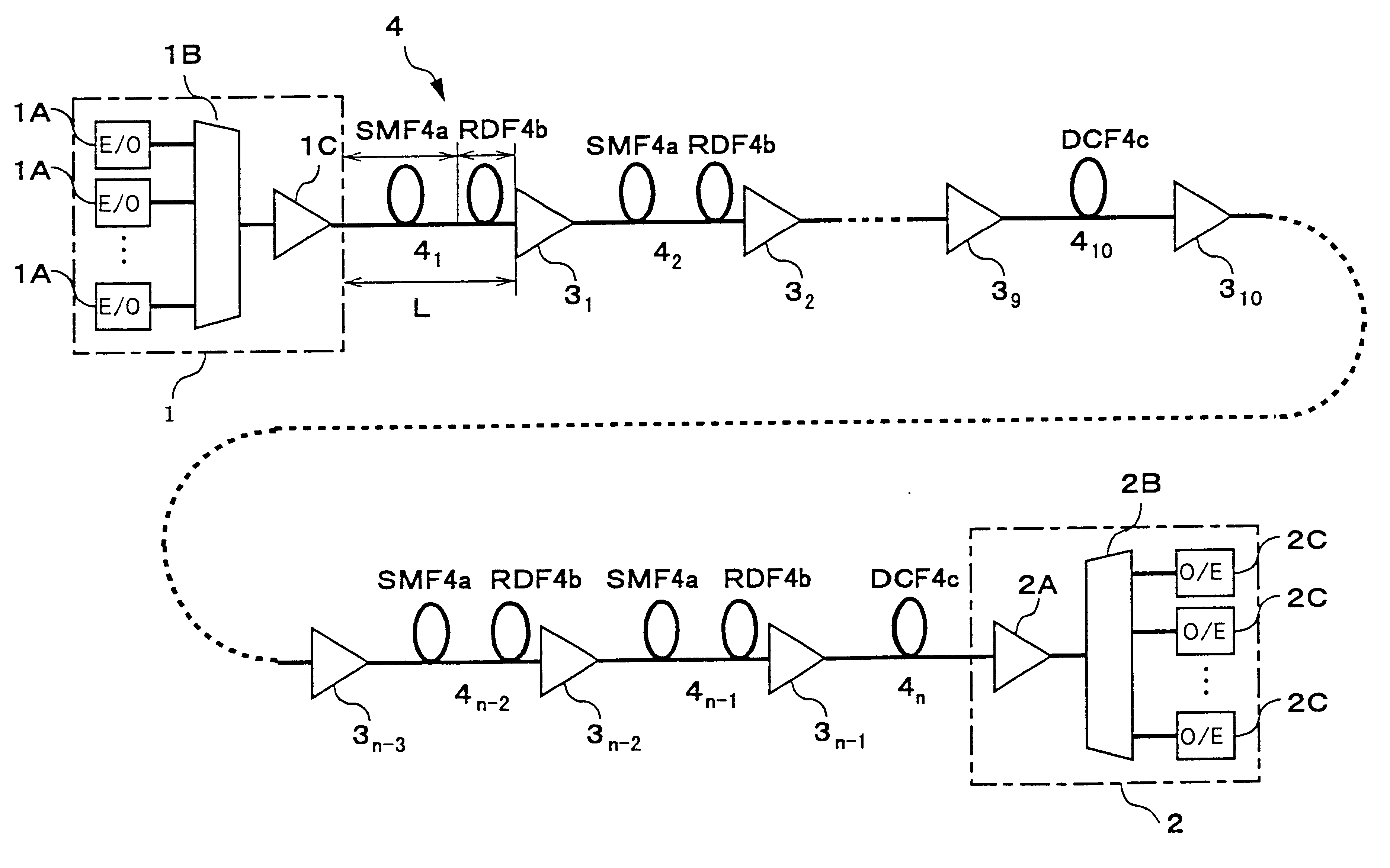
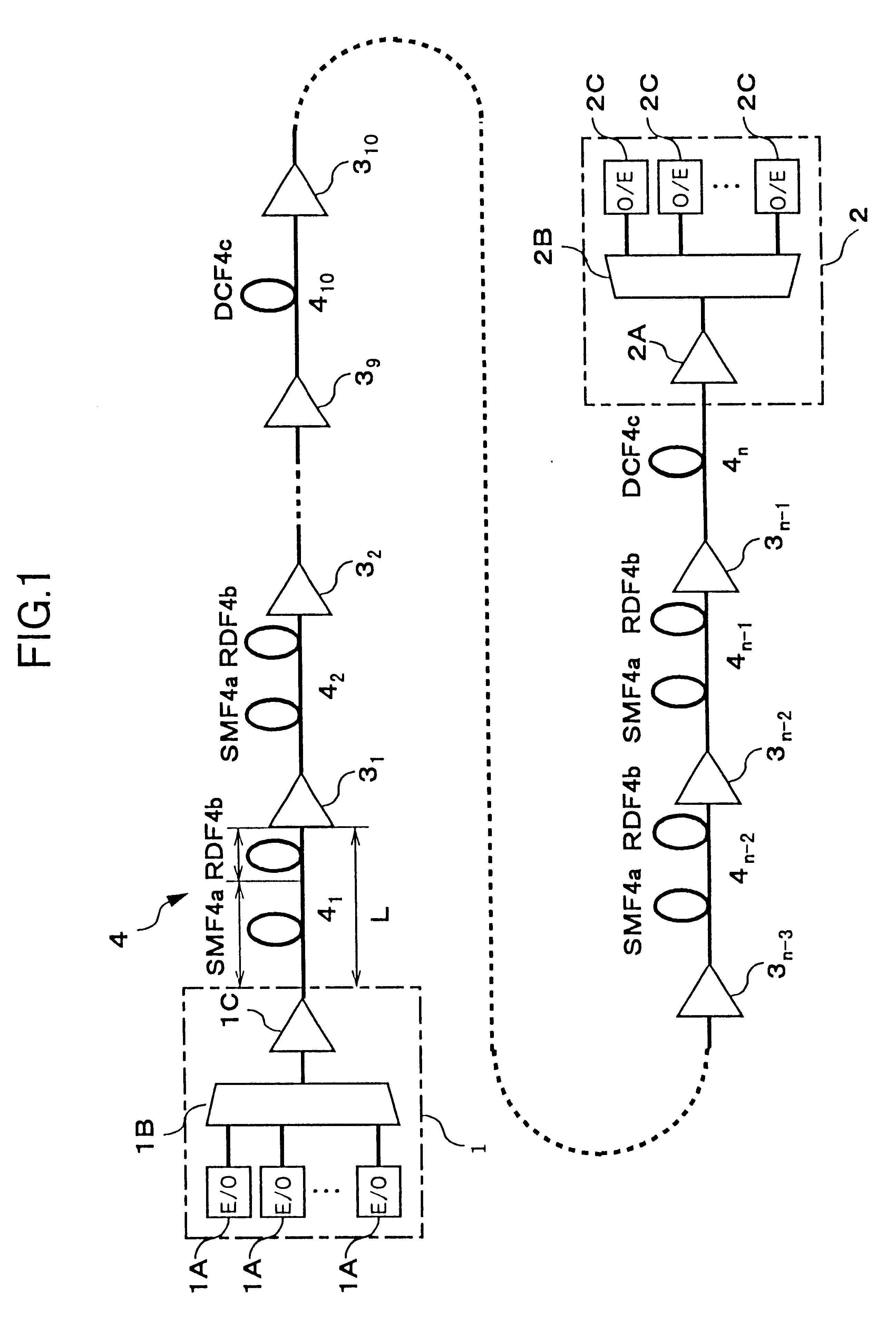
FIG. 1 is a block diagram showing a basic configuration of a WDM optical transmission system in accordance with a

The WDM optical transmission system shown in FIG. 1 consists of, for example, an optical transmitter station 1, an optical receiver station 2, a plurality of optical amplifiers (optical repeaters) 3.sub.1, 3.sub.2, etc., and an optical fiber transmission line 4. The plurality of optical amplifiers is arranged between the transmitter and receiver stations at required intervals. The optical fiber transmission line 4 links the optical transmitter station 1, the respective optical amplifiers 3.sub.1, 3.sub.2, etc., and the optical receiver station 2.

The optical transmitter station 1 includes a plurality of optical transmitters (E / O) 1A, a multiplexer 1B, and a post-amplifier 1C. The plurality of optical transmitters (E / O) 1A outputs a plurality of optical signals having different wavelengths. The multiplexer 1B wavelength division multiplexes the plurality of optical signals ...

second embodiment

Next, the present invention will be described below.

In the aforesaid first embodiment, cumulative wavelength dispersion generated in each hybrid transmission line is compensated for at required compensation intervals such as ten spans, and thus converged to nearly zero. However, according to this method of compensating for cumulative wavelength dispersion, similarly to the conventional method described in conjunction with FIG. 19, a state in which cumulative wavelength dispersion becomes positive is repeated periodically. When cumulative wavelength dispersion becomes positive, the peak value of optical power increases due to effect of optical pulse compression, to thereby become susceptible to a nonlinear effect. In the second embodiment, by taking a countermeasure in order to always keep cumulative wavelength dispersion negative, the nonlinear effect is prevented from being generated to thereby improve a transmission characteristic.

FIG. 11 is a block diagram showing a basic configu...

third embodiment

Next, the present invention will be described below.

According to a WDM optical transmission system in accordance with the third embodiment, residual wavelength dispersion-slope that could not be compensated for by the optical fiber transmission line 4 in the aforesaid embodiments is compensated for to thereby further improve a transmission characteristic.

FIG. 14 is a block diagram showing a schematic configuration of a WDM optical transmission system of the third embodiment.

Referring to FIG. 14, the WDM optical transmission system has, in addition to the same components as those of, for example, the first embodiment, residual wavelength dispersion-slope compensators 1E and 2E. The residual wavelength dispersion-slope compensators 1E and 2E serving as residual wavelength dispersion-slope compensation units are provided in the optical transmitter station 1 and optical receiver station 2 respectively. The other components are identical to those of the first embodiment.

Each of the resid...


PUM


Abstract

An object of the present invention is to provide a WDM optical transmission system with an excellent transmission characteristic by employing a hybrid transmission line which is formed by combining under optimal conditions an optical fiber having positive wavelength dispersion, and an optical fiber having negative wavelength dispersion. According to the WDM optical transmission system, an optical transmitter station, optical amplifiers, and an optical receiver station are interconnected over an optical fiber transmission line. The optical fiber transmission line has an inter-repeater segment formed with a hybrid transmission line composed of a 1.3 mum zero-dispersion SMF and an RDF, and an inter-repeater segment formed with a DCF for compensating for cumulative wavelength dispersion generated in the hybrid transmission line. As the conditions for setting the hybrid transmission line, a ratio of the length of the RDF to the length of the inter-repeater segment must be 20% or more and 40% or less. Consequently, an influence due to a nonlinear effect or transmission loss in the hybrid transmission line can be minimized to thereby improve a transmission characteristic.

Description

1. Field of the InventionThe present invention relates to a wavelength division multiplexing optical transmission system for carrying out repeating transmission of a wavelength division multiplexed signal light via optical amplifiers. More particularly, this invention relates to a wavelength division multiplexing optical transmission system in which a hybrid transmission line formed by combining optical fibers having reciprocal wavelength dispersion is adopted for compensating for wavelength dispersion and wavelength dispersion-slope.2. Description of the Related ArtIn the past, with long-distance optical transmission systems, optical reproduction repeaters have been used for transmission. The optical reproduction repeaters convert an optical signal into an electrical signal and perform re-timing, reshaping, and regenerating. However, the employment of optical amplifiers has come to be a matter of common practice these days. An optical amplification repeater transmission mode using ...

Claims


Application Information

Patent Timeline
IPC IPC(8): H04B10/18H01S3/10H04B10/2507G02B6/02H04B10/2525H04B10/2543H04B10/291H04J14/00H04J14/02
CPCH04B10/25253
Inventor TANAKA, TOSHIKINAITO, TAKAO
Owner FUJITSU LTD
Why Eureka
Try Eureka